20
ENGLISH
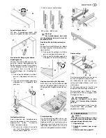
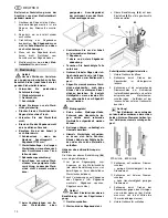
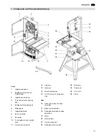
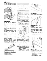
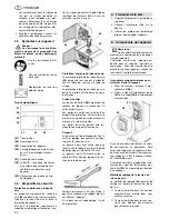
Saw table lateral alignment
1.
Loosen lock lever
(53)
and hexagon
nut
(54)
.
A
Danger!
Risk of injury, even with the
band saw blade at standstill. To
loosen and tighten the fastening
screws use a tool that allows for
keeping your hand at a sufficient dis-
tance from the band saw blade.
2.
Loosen the three fastening screws
(55)
.
3.
Align saw table so that the blade
runs through the centre of the table
insert's slot.
4.
Tighten the three fastening screws
(55)
again.
5.
Tighten hexagon nut
(54)
only so
much that the saw table can still
easily be tilted.
6.
Tighten lock lever
(53)
.
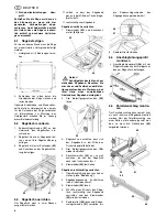
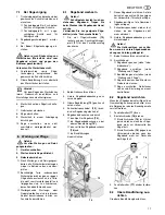
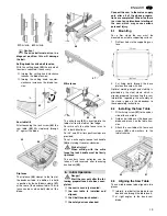
Aligning the saw table at right angles
to the band saw blade
1.
Raise upper blade guide fully (see
"Operation").
2.
Check band saw blade tension (see
"Initial operation").
3.
Loosen lock lever
(53)
.
4.
Using a try square, set the table at
right angles to the blade and tighten
the lock lever
(53)
again.
5.
Loosen lock nut
(56)
and adjust limit
stop screw
(57)
until it touches the
saw housing.
6.
Tighten lock nut.
6.4
Installing the Fence
Guide Extrusion
x
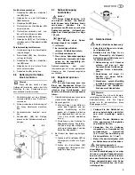
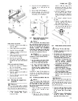
Fasten the fence guide extrusion
(58)
with four each thumb screws
and washers to the saw table.
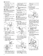
6.5
Installing the Rip Fence
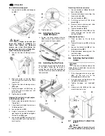
The rip fence can be used on both sides
of the blade. When the rip fence is
moved from one side of the saw blade to
the other the fence extrusion
(60)
needs
to be reversed.
Reversing the fence extrusion
1.
Loosen knurled nut
(64)
of the hold-
down clamp
(63)
.
2.
Remove hold-down clamp from the
fence extrusion
(60)
.
3.
Loosen knurled nut
(62)
.
4.
Pull fence extrusion off the fence
bracket
(61)
.
5.
Reverse fence extrusion and slide
back on the fence bracket.
6.
Tighten knurled nut
(62)
.
7.
Slide hold-down clamp
(63)
on the
fence extrusion and secure with
knurled nut
(64)
.
Clamping the rip fence
1.
Place rip fence on the rip fence
guide.
2.
Tighten the lock lever
(59)
of the rip
fence.
3.
Loosen the knurled nut
(64)
of the
hold-down clamp
(63)
.
4.
Slide hold-down clamp against the
rear table edge.
5.
Tighten the knurled nut
(64)
.
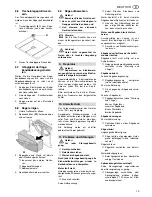
6.6
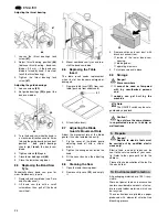
Installing the Push Stick
Holder
3
Note:
If the saw is to be mounted on the
stand, the push stick holder can only be
installed afterwards.
1.
Turn a hexagon nut on a cap screw
(65)
, all the way up to the
unthreaded part of the shank.
2.
Turn cap screw into the hole on the
left side of the band saw.
3.
Tighten hexagon nut hand-tight
only.
4.
Hang push stick
(66)
on the cap
screw when not in use.
6.7
Connection of a Dust Col-
lector
A
Danger!
Some types of saw dust (e.g. of
oak, beech and ash wood) may cause
54
53
55
57
56
58
59
60
61
62
63
64
65
66
Содержание BAS 317 Precision WNB
Страница 53: ...ZA0091_1 fm 3 1 2 4 6 5 ...
Страница 54: ......
Страница 55: ......
Страница 56: ...U4BA_M1 FM ZINDEL AG Technische Dokumentation und Multimedia www zindel de www metabo com ...

