2. Installation
User Manual 13
I/O Contacts
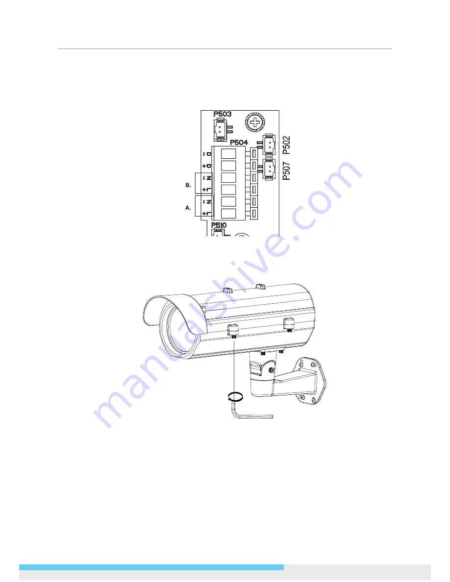
Connect the power cable to the power port of the AC24V camera and to the A section (L+: power +/
N-: power- ) as below. And connect the outside AC24V power supply to the section B( L+: power+/
N-: power- ).
Contact positions on the heater board
5. After you have finished wiring the Ethernet cable, close the side cover and use the provided
screws to fix the housing on the bracket with the hexagonal wrench.


