background image

6

1

2

3

4

5

7

OFF

COLDER

NI1404-120

17

18

CO

2


6

1

2

3

4

5

7

OFF

COLD

ER

FILL ICE BANK

IN CO2

IN WATER

18.1

T

R

N

G

B

1

1

2

3

3

2

6.1

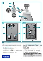
CIRCUIT FILLING

•  Turn on the water tap and make sure there are no leaks.
•  Adjust thermostat

1

 in the maximum position.

•  Turn on the main ON/OFF switch

3.

•  Press the sparkling water button

 until all the remaining air is eliminated 

from the circuit.

•  Repeat the operation with the cold water button

6.2

CONNECTION TO THE CO2 CYLINDER (WG models)

For the production of carbonated water, you must provide a CO

2

 cylinder 

for alimentary use.

For cylinder dimensions and capacity, please refer to the “technical

characteristics” chapter.

•  Extract the front panel.
•  Connect the pressure reducer

to the CO

2

cylinder 

B

, making sure the 

gasket 

is in the correct position.

•  Tighten nut

and check that the pipe 

(outlet) is well connected.

•  Place the cylinder and reducer within the appliance, in the predisposed

housing.

•  The bottle has to be fixed with the special included pieces.

In counter top and under counter versions, the cylinder is 
placed outside the appliance.
In the ground versions, the cylinder can be housed inside the 
cabinet, as long as it falls within the maximum dimensions: 
height 87 cm, diameter 17 cm.

6

STARTING

GB

Warning! If the appliance has been laid down or turned upside 
down, you should wait at least 8 hours before starting it.

13

Содержание NIAGARA

Страница 1: ...I GB D F E Installation use and maintenance handbook Rel 150905 NIAGARA COD 5561397 Rev 0 0210 1 ...

Страница 2: ...er within 24 hours In order to use your appliance to its best we advise reading these instructions carefully as they contain useful information Make sure that installation and electrical wiring are carried out by a qualified technician according to the manufacturer s instructions and to the local norms in force The electrical system must be equipped with an effective earth according to the law 46 ...

Страница 3: ...he socket and contact the local retailer or technical service assistance Use of the machine in these conditions could cause fires or electric shocks Periodically disconnect the machine from the socket and clean the plug and socket with a dry cloth If the machine is connected in a place exposed to dust smoke or high humidity the dust accumulated on the plug will absorb humidity and this could alter...

Страница 4: ...ion This appliance does not contain CFCs the cooling circuit contains a gas that is not harmful to the ozone layer For further details please refer to the serial data plate on the appliance Produkt This appliance is marked according to the European directive 2002 96 EC on Waste Electrical and Electronic Equipment WEEE By Ensuring this product is disposed of correctly you will help prevent potentia...

Страница 5: ... in various settings ranging from cafés restaurants canteens hospitals public places offices and domestic environments they should always be installed indoors and in the environmental conditions described under the technical features heading They are equipped with an internal cooling system capable of supplying water cooled to 3 10 C They use a direct cooling system ice bank The following models a...

Страница 6: ...t 6 5 No water warning light WG models 7 Load ice compartment ø 8mm 8 Data plates 9 Distribution nozzle positioned in a protected area 10 Mains water inlet ø 8mm or 3 4 M 11 Power supply cable 12 Drain water ø 24mm and overflow ice compartment 13 Removable panel for compressor maintenance 14 Adjustable levelling feet 15 Main ON OFF switch 16 Cold water thermostat 17 Removable panel of the distribu...

Страница 7: ...ad ice compartment ø 8mm 13 Ice compartment drain too full 15 CO2 inlet ø 8mm WG models GB 3 2 COUNTERTOP MODELS TOP 3 3 UNDERCOUNTER MODELS IN 1 Cold water thermostat 2 Electrical power supply socket 3 Main switch 5 Mains water inlet ø 8mm or 3 8 F 7 Load ice compartment ø 8mm 8 Cold water outlet ø 8mm OUT WATER 9 Outlet for water at room temperature ø 8mm OUT AMBIENT 10 Sparkling water outlet ø ...

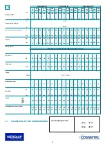
Страница 8: ...A B 338 H 818 IN 65 IN 65 WG IN 120 IN 120 WG TIN 180 IN 180 WG A 420 480 530 B 350 350 350 H 500 500 500 TOP 65 TOP 65 WG TOP 120 TOP 120 WG TOP 180 TOP 180 WG A 370 370 370 B 422 482 532 C 495 495 495 D 345 345 345 H 510 510 510 65 SL 120 SL 180 SL 65 SLWG 120 SLWG 180 SLWG A 405 560 B 480 480 H 1480 1480 8 ...

Страница 9: ...4 5 10 1 6 500 37 81 5 160 70 dB 120 31 7 70 18 5 6 5 14 3 1 3 500 37 81 5 250 70 dB 65 17 2 40 10 6 4 5 10 1 6 300 32 71 160 70 dB 65 17 2 40 10 6 4 5 10 1 6 500 40 88 160 70 dB 120 31 7 70 18 5 6 5 14 3 1 3 500 40 88 250 70 dB 180 47 5 100 26 4 11 5 25 3 1 3 500 52 115 390 70 dB 180 WG 120 WG 120 31 7 70 18 5 6 5 14 3 1 3 800 48 106 250 70 dB 180 WG 180 47 5 100 26 4 11 5 25 3 1 3 500 51 112 390...

Страница 10: ...nce is not suitable for outdoor use and it is also not recommended to install it in very damp rooms Adjust the feet in ground models 1 to make the structure level fig 7 The appliance should be positioned in such a way as to leave approximately 10 cm of space free S for air to circulate freely the condenser side must be easily accessible for cleaning 5 INSTALLATION GB 10 ...

Страница 11: ...nection check that the network pressure is between 2 and 3 bar and flow more than 3 5 l min If the mains pressure is below 2 bar or the flow rate is less than 3 5 l min fit a device capable of increasing the mains pressure such as an autoclave or similar 5 INSTALLATION GB During connection of the appliance to the mains water supply all pre existing tubes gaskets and joints placed between the appli...

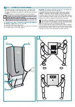
Страница 12: ...r is eliminated from the draining 13 fig 15 Take off tube T from the connection 7 and connect it in the connection 1 in water exerting pressure as shown on picture 11 IN models or picture 14 TOP and FLOOR models The connection 7 fill ice bank has to be 5 3 ELECTRICITY CONNECTION Connection to the mains electricity supply is carried out by connecting the plug to a mains socket fig 16 The supply soc...

Страница 13: ...ions and capacity please refer to the technical characteristics chapter Extract the front panel Connect the pressure reducer R to the CO2 cylinder B making sure the gasket G is in the correct position Tighten nut N and check that the pipe T outlet is well connected Place the cylinder and reducer within the appliance in the predisposed housing The bottle has to be fixed with the special included pi...

Страница 14: ...ue should be of 3 4 bars This value is set at the factory If necessary turn screw 4 Turn tap 2 of the CO2 cylinder Press the pushbutton for carbonated water Let a few litres of water flow until carbonated water begins to come out Attention Upon occurred installation a correct flow of carbonated water takes about 20 seconds to distribute 1 litre Attention The results of pressure variations on carbo...

Страница 15: ...the appliance or when replacing the CO2 cylinder or if the water cooler has no water left inside it a few air bubbles may enter the carbonation device These air bubbles could diminish the quality of the carbonation process and we therefore recommend you remove them Close the CO2 cylinder Drain the circuit by pulling the outlet valve ring V Reopen the CO2 cylinder Drain off at least two litres of s...

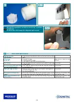
Страница 16: ...resent Every week Cleaning the mechanical water filter TOP and GROUND models Disassemble the inlet pipe fitting pull the filter using pliers and remove any impurities fig 21 Every month Cleaning the fridge condenser Remove any dust or dirt using a vacuum cleaner or similar appliance Do not use compressed air jets Do not use metal brushes Every month Cleaning the water dispensing spouts Remove the ...

Страница 17: ...ea UV bulb if present Wear protection latex disposable gloves to avoid touching the lamp with your hands The contact with the skin can prejudice the duration of the lamp Enter the appliance near to the distribution area Unscrew the tightening screw and remove the cover fig 22 remove the lamp and replace it with one of the same kind mount again all the components in reverse E v e r y 6 0 0 0 hours ...

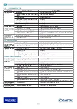
Страница 18: ...In the INTERVENTION column the corresponding corrective action is listed GB 8 INTERNAL CLEANING HYGIENIC CLEANING WARNING Considering that the products used for the hygienic cleaning are acid and alkali corrosive substances disposable gloves must be used as well as glasses to protect your eyes When this hygienic cleaning is carried out you must keep to the product reaction times percentages of hyg...

Страница 19: ...sure they do not touch any other parts l acqua fredda esce piano o non esce low pressure of the inlet water take steps to increase the pressure autoclave faulty solenoid valve replace it clogged water filter replace it the temperature adjuster is faulty and causes complete freezing of the ice compartment make the ice melt replace the temperature adjuster CARBONATING SYSTEM the carbonated wa ter is...

Страница 20: ...MERQUIP LTD NZ DISTRIBUTORS 58 Walls Road Penrose Auckland 1061 PO Box 13 927 Onehunga Auckland 1643 Free Phone 0800 636 0 636 T 09 636 0 636 F 09 636 8 636 E info merquip co nz www merquip co nz 20 ...

Отзывы: