background image

PowerGuard 

PRO


User & Installation Guide Rev A


Page 7 


Installation 


Warning!   

Isolate power supply before starting installation.


Positioning of Parts 

The following should be observed as parts of PowerGuard

 PRO

 are designed for wet/dirty environments, 

but others are not.  
 

Main CPU. 

Caution! 

Damage will occur if the CPU is allowed to get wet.


Warning! 

Do not install the CPU in a petrol/gas engine room environment. 


The CPU is designed for location in a dry environment (such as on cab side of engine room bulkhead 
or a cupboard). It is suitable for installation in drier engine compartments on boats. However, it is not 
sealed against moisture ingress. The CPU is 

NOT

 suitable for installation or operation in atmospheres 

where there is a risk of ignition or explosion. 
 

Contactors 

These  are  designed  to  be  installed  under  hood,  in  wet  engine  room  environments  and  battery 
compartments. The contactors are IP66 rated and will withstand hose downs. The contactor should 
be located as close as possible to the associated battery. 
 

Isolator & Reset Switches 

Normally located on dash panels or alongside engine controls. They are IP66 rated from the front 
and may be located in exterior positions. 


Содержание PowerGuard PRO

Страница 1: ...m User Installation Guide Revision A Merlin Equipment Ltd Clyst Court Hill Barton Industrial Estate Exeter Devon EX5 1SA United Kingdom T 44 0 1202 697979 Merlin Power Systems 332 4 West Montauk Highway Hampton Bays New York NY11946 United States of America T 1 631 594 5102 www merlinequipment com ...

Страница 2: ...uard PRO is designed for installation by qualified and competent electrical engineers Qualified and competent engineers will be familiar with safe working practices local health safety legislation and the proper and safe use of tools and equipment Therefore not all obvious practices that may lead to system damage injury or death are detailed within this manual If you are in anyway unsure about any...

Страница 3: ...lectric shock damage or other injury FUSES Use the correct ampere rating when replacing fuses Failure to do so may result in fire injury electric shock or damage DO NOT install or operate the CPU in an explosive atmosphere DO NOT install or expose the CPU to excessive temperatures or humidity If in any doubt consult a suitably qualified and competent engineer or the supplier DO NOT substitute Cont...

Страница 4: ...s of EU Electromagnetic Compatibility EMC Directive 2014 30 EU PowerGuard PRO complies with RoHS Reduction of Hazardous Substances Directive 2011 65 EC At the end of life PowerGuard Pro should be disposed of as normal electrical waste PowerGuard PRO has been tested to and surpasses ISO 7637 2 for use on vehicles Signed James Hortop Managing Director Merlin Power Systems UK Date 18th January 2019 V...

Страница 5: ...nition is switched on PowerGuardPRO may be used on 1 or 2 battery bank installations at either 12 or 24VDC Those battery banks may also be of mixed voltage e g a 12 and a 24V battery bank Please take the time to read and understand this manual before installation and use Please note that this manual refers to the PowerGuardPRO retail product PowerGuardPRO is available in an OEM version The OEM ver...

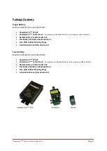
Страница 6: ...or Switch x1 Flat Battery Protection Reset Switch x1 Fuse Kit Rubber Blanking Plugs Installation Manual this document Twin Battery Models 04 8103 12V and 04 8104 24V PowerGuard PRO CPU x1 PowerGuard PRO Contactor x2 Part Numbers SU80 5164MPL 12V or Part Numbers SU80 5165 24V Remote Battery Isolator Switch x2 Flat Battery Protection Reset Switch x1 Fuse Kit Rubber Blanking Plugs Installation Manual...

Страница 7: ...gine room bulkhead or a cupboard It is suitable for installation in drier engine compartments on boats However it is not sealed against moisture ingress The CPU is NOT suitable for installation or operation in atmospheres where there is a risk of ignition or explosion Contactors These are designed to be installed under hood in wet engine room environments and battery compartments The contactors ar...

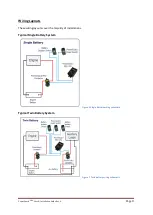
Страница 8: ...on Guide Rev A Page 8 Wiring Layouts These wiring layouts cover the majority of installations Typical Single Battery System Figure 1 Single battery wiring schematic Typical Twin Battery System Figure 2 Twin battery wiring schematic ...

Страница 9: ...serve correct polarity of Contactor wiring will result in incorrect operation of the system and may cause serious damage Serious damage to the PowerGuardPRO will occur if the wires to the Contactor coils are incorrectly connected or short circuited Contactor Rating Contactors are rated for charging systems of up to 200A Continuously They will also handle intermittent cranking current of engines up...

Страница 10: ...Remote Battery Switching The Battery Isolator switches control connection or disconnection of the battery or batteries PowerGuard PRO can switch up to 2 independent battery banks Flat Battery Protection PowerGuardPRO can prevent a flat battery condition by disconnecting the battery or batteries from the load It achieves this by monitoring the battery voltage levels If the voltage level falls below...

Страница 11: ...rrectly Caution Warning Do NOT overtighten However failure to tighten the stud nuts adequately may result in an intermittent connection and or arcing which may cause overheating or ignition CPU Caution Damage will occur if the CPU is allowed to get wet Warning Do not install the CPU in a petrol gas engine room environment The CPU is designed for location in a dry environment such as on cab side of...

Страница 12: ...h temperature thin wall low voltage cable suitable for use in automotive marine and allied industries By Pass Loads There may be certain loads attached to the battery that should not be subject to Flat Battery Protection disconnection For example some engine management computers hazard warning lights etc In some states countries these this may be mandated by law Bypass loads should be identified i...

Страница 13: ...t voltage for battery 1 Single battery system B2 VOLTS Sets the internal threshold disconnect voltage for battery 2 Twin battery system TIME DELAY Adjusts the functional time delay the delay prevents relay chatter The range of controls is B1 PowerGuard 1 voltage threshold range 10 5 to 12 7 V DC 21 0 to 25 4 V DC for 24V unit B2 PowerGuard 2 voltage threshold range 10 5 to 12 7 V DC 21 0 to 25 4 V...

Страница 14: ...o provide advice if required While the trim pots may be adjusted while PowerGuardPRO is powered up we recommend removing the B1 and B2 sense fuses to prevent accidental shorting of components on the PCB and potential PowerGuard PRO damage Adjustments to trim pot settings should be carried out using an insulated trimming tool A small 1 5mm flat blade screwdriver can be used but extra care is requir...

Страница 15: ...he ignition is switched on you MUST NOT release the vehicle boat into service Severe damage and potentially hazardous situations may occur if B1 is disconnected when the engine is running 4 Turn the ignition off Note the voltage of B1 Apply loads to B1 When the voltage drops below the pre set disconnect voltage for a period exceeding the pre set Time Delay you should hear the B1 Contactor disconne...

Страница 16: ...PowerGuard PRO User Installation Guide Rev A Page 16 Product Specifications ...

Страница 17: ... product defect within the Warranty Period and provided that Merlin through inspection establishes the existence of such a defect and that it is covered by this Limited Warranty Merlin will at its option use new and or reconditioned parts in performing warranty repair and building replacement products Merlin reserves the right to use parts or products of original or improved design in the repair o...

Страница 18: ... Installation Guide Rev A Page 18 REVISION PAGE NOT FOR PUBLICATION Rev1 3 Correcting E number Page4 V1 2 erroneously showed SmartBank Pro E number Rev1 3 Track changes set Rev A Updates to standards and general revisions ...

Отзывы: