PowerGuard
PRO
User & Installation Guide Rev A
Page 11
Location and Connections
Prior to installation ensure that the vehicle/boat is safely secured and the power is
isolated. For example remove ignition keys, disconnect batteries, ensure parking brake is
secured etc. Only connect the power feed fuses to PowerGuard
PRO
once all wiring is
completed and checked.
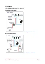
Install the PowerGuard
PRO
following the schematic shown in Figure 3.
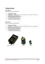
Contactor(s)
The Contactor(s) should be located adjacent to the batteries which are being protected. They may
be installed under hood or within exterior lockers. The wiring and connectors used should be rated
appropriately.
The main high-power cables should be terminated with heavy-duty crimp ring terminal suitable for
M8 stud. The stud nuts should be tightened to a torque of 11 to 12 Nm.
Warning!
Incorrectly specifying the cable current rating or inadequate cable termination could result
in malfunction, fire, injury or serious damage.
Caution & Warning!
Observe carefully B1 (Battery 1) and B2 (Battery 2) designations. B1 is always
the engine battery, B2 is always the auxiliary battery. Any changes from this will require advanced
set up. If B1 and B2 are transposed, the system will not operate correctly.
Caution & Warning!
Do NOT overtighten. However, failure to tighten the stud nuts adequately may
result in an intermittent connection and/or arcing which may cause overheating or ignition.
CPU
Caution!
Damage will occur if the CPU is allowed to get wet.
Warning!
Do not install the CPU in a petrol/gas engine room environment.
The CPU is designed for location in a dry environment (such as on cab side of engine room bulkhead
or a cupboard). It is suitable for installation in drier engine compartments on boats. However, it is not
sealed against moisture ingress. The CPU is
NOT
suitable for installation or operation in atmospheres
where there is a risk of ignition or explosion.
Isolator and Reset Switches (Emergency Override)
These are usually mounted in locations such as dashboards or helm panels without needing to run
heavy duty cables throughout the vehicle/boat. The switches are IP66 rated and fully waterproof.
Ignition Inhibit (‘Ignition Feed’ Wire –
see Figure 3)
Caution & Warning!
Failure to connect the ignition inhibit may cause damage to the engine
alternator and all electrics/electronics on board. Furthermore, critical loads like electric power
steering may cease to operate. ALWAYS connect the ignition inhibit wire
.
The Ignition Inhibit MUST be connected to the engine’s ignition switch. When the ignition is on,
PowerGuard
PRO
is disabled and will not disconnect batteries. The remote battery switches will not
work.


