MM-34
Revised 11-02
Page 7
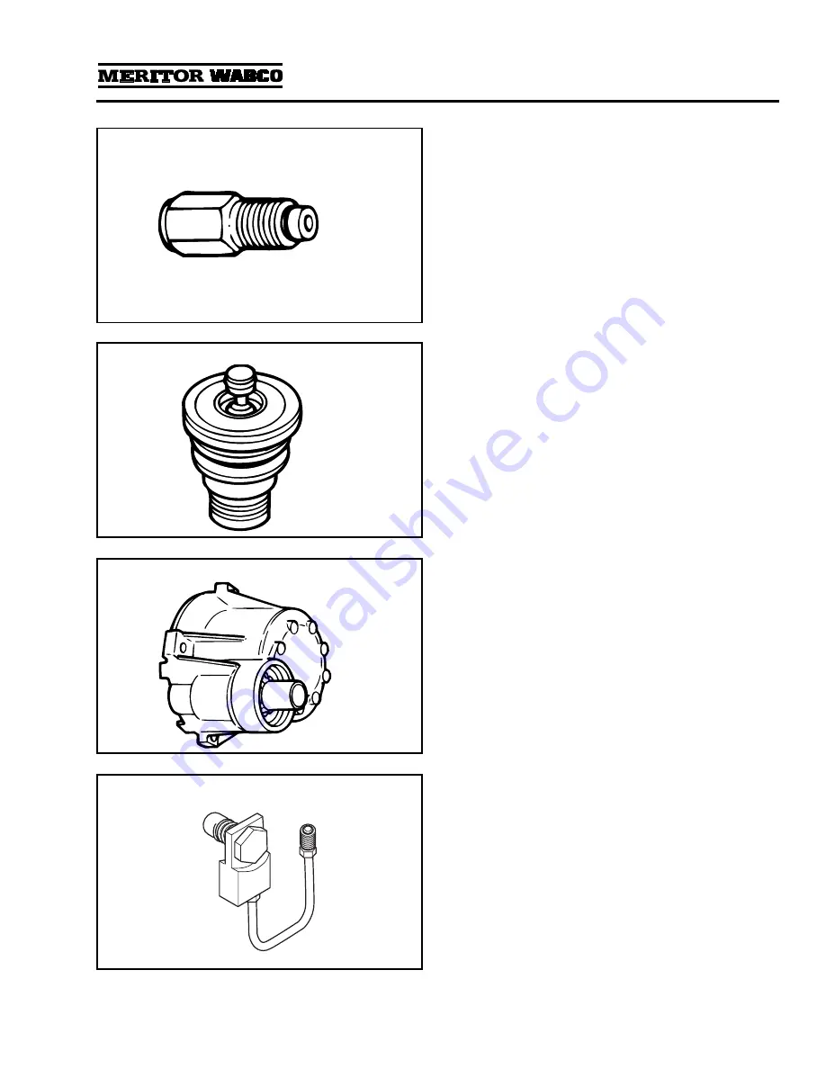
Figure 1.11
Pressure Relief Valve:
A valve that protects the
air dryer from over-pressurization. On dryers
with date codes earlier than 2295, it is installed
in the inlet port of the dryer (port 1) using a
Street-Tee fitting. On dryers with date codes later
than 2295, the pressure relief valve is attached
directly to the air dryer.
Figure 1.11
.
1002153a
Figure 1.12
Purge Valve:
A valve located on the bottom of
the air dryer base that remains open during a
compressor unload cycle. It allows collected
moisture, condensation, and contamination to
be expelled from the air dryer during a purge
cycle.
Figure 1.12
.
1002154a
Figure 1.13
Regeneration Valve:
The valve that controls
regeneration of the desiccant. It allows air from
the supply and secondary tanks to bypass the
outlet check valve. The air expands and
backflushes moisture off of the desiccant, then
out through the dryer’s purge valve.
Figure 1.13
.
Not used with “P” style dryers.
1002155a
Figure 1.14
ECON Valve Replacement Part:
This valve is
used on System Saver Series 1200E single
cartridge air dryers used with Holset E-type
compressors.
Содержание System Saver 1000
Страница 4: ...Notes...
Страница 40: ...Notes...
Страница 41: ...Notes...
Страница 42: ...Notes...
Страница 43: ......


