14
Quintessence User Manual
© 2007 Merging Technologies
Mykerinos Connection
•
J6 –
16 pin ribbon cable to the primary (master) Mykerinos card for TimeCode and sync. In order for
the MTCHIO Sync board’s TimeCode & Video functionalities to be fully operational, it is necessary to
connect the
J6
socket to the primary (TimeCode Master) Mykerinos card, with the 16 pin ribbon cable
provided. In multi-board systems, by convention, the primary Mykerinos card is the one fitted in the PCI
slot closest to the graphics adapter.
Note
: video termination Jumper 4 on the TimeCode Master
Mykerinos should be set to
OPEN
when used in conjunction with MTCHIO.)
Jumpers and Power
•
JP1
– 75
Ω
termination for the Word clock input signal
•
JP2
– 5V from the PC power supply through the Molex (
J2
) connector (hard disk type connector)
•
JP3
– 5V from the Mykerinos board through the 16 pin ribbon cable connected to the Video/TC
header.
The internal Molex connector
J2
is used to p12V to the rear fans through
JP4
and
JP5
terminals. It
also provides alter5V to the
MTCHIO
module through jumper
JP2
.
WARNING:
Never close
JP2
and
JP3
at the same time.
Power and Fan Connectors
•
J2
Molex connector takes power from PC PSU
Detailed pinout of
J2
:
•
JP4
&
JP5
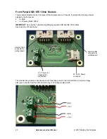
p12V to the rear panel fans of the chassis. Here is the pinout of
JP4
and
JP5
.
+12V GND
+12V
GND
GND
+5V
JP4 JP5
J2
Содержание Quintessence
Страница 1: ......


