background image


www.avsl.com

                                                600.105UK User Manual


RESISTANCE MEASUREMENT 

1.


Red lead to “VΩmA”. Black lead to “COM”.


2.


Set RANGE switch to desired 

Ω

 position. 

3.


If the resistance being measured is connected to a 

circuit, turn off the power and discharge all capacitors 

before measurement. 

4.


Connect test leads to circuit being measured. 

5.


Read resistance value on Digital Display. 


DIODE MEASUREMENT 

1.


Red lead to “VΩmA”, Black lead to “COM”.


2.


Set 

RANGE switch to “

” position.


3.


Connect the red test lead to the anode of the diode to 

be measured and black test lead to cathode. 

4.


The forward voltage drop in mV will be displayed. If 
the diode is reversed, the 

figure “1” will be shown.


TRANSISTOR hFE MEASUREMENT   

1.


Set RANGE switch to the hFE position. 

2.


Determine whether the transistor is PNP of NPN type 

and locate the Emitter, Base and Collector leads. 
Insert the leads into the proper holes of the hFE 

Socket. 

3.


The meter will display the approximate hFE value at 

the condition of base current 10μA and V

CE

2.8V. 

 
AUDIBLE CONTINUITY TEST 

1.


Red lead to “VΩmA”, Black lead to “COM”.


2.


RANGE switch to “ ” position.


3.


Connect test leads to two points of circuit to be tested. 

Содержание 600.105UK

Страница 1: ...Please read this manual thoroughly and ensure all contents are fully understood before use of the apparatus WARNING MTN01 Network Digital Multimeter Item Ref 600 105UK EN61010 1 2010...

Страница 2: ...ltage as marked on the meter between the terminals or between any terminal and grounding The rotary switch should be placed in the right position and no changeover of range should be made during measu...

Страница 3: ...e meter and accidents A soft cloth and mild detergent should be used to clean the surface of the meter on a regular basis No abrasives or solvents should be used to prevent the surface of the meter fr...

Страница 4: ...LCD 3 digits 1999 count 0 5 high Polarity Automatic indicated minus assumed plus Measure method double integral A D switch implement Sampling speed 2 times per second Over load indication 1 is display...

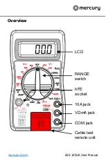
Страница 5: ...www avsl com 600 105UK User Manual Overview COM jack V mA jack 10A jack hFE socket LCD RANGE switch Cable test remote unit...

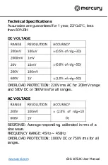
Страница 6: ...for 1 year 23 5 less than 80 RH DC VOLTAGE OVERLOAD PROTECTION 220V rms AC for 200mV range and 500V DC or 500Vrms for all ranges AC VOLTAGE RESPONSE Average responding calibrated in rms of a sine wav...

Страница 7: ...sounds if resistance is less then 30 20 OVERLOAD PROTECTION 15 seconds maximum 220Vrms DC CURRENT OVERLOAD PROTECTION 500mA 250V fuse 10A range infused MEASURING VOLTAGE DROP 200mV RESISTANCE RANGE R...

Страница 8: ...rn on power of the device or circuit being measured and the voltage value will appear on the Digital Display along with the voltage polarity DC CURRENT MEASUREMENT 1 Red lead to V mA Black lead to COM...

Страница 9: ...est lead to the anode of the diode to be measured and black test lead to cathode 4 The forward voltage drop in mV will be displayed If the diode is reversed the figure 1 will be shown TRANSISTOR hFE M...

Страница 10: ...6 7 8 G RJ45 Remote unit 1 2 3 4 5 6 7 8 G Main unit 1 2 3 4 5 6 RJ11 Remote unit 1 2 3 4 5 6 FAULT DESCRIPTIONS 1 If one cable is open circuit eg no 3 then the no 3 LED on both units wont illuminate...

Страница 11: ...remove the 2 screws in the bottom of the case simply remove the old and replace with a new one Be careful to observe polarity ACCESSORIES Operator s instruction manual Set of test leads red and black...

Отзывы: