2)
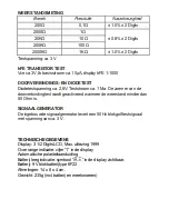
Determine whether the transistor to be tested is PNP or NPN type
and locate the emitter, base, collector leads. Insert the leads into
the proper holes of the "hFE" socket on the front panel. The meter
will display the approximate hFE value.
DIODE MEASUREMENT
1)
Connect the red test lead to the "V
Ω
mA" jack and the black test
lead to the "COM" jack.
2)
Set the Function / Range switch to the "
" range.
3)
Connect the red test lead to the anode of the diode to be tested
and the black test lead to the cathode of the diode.
4)
The approximate forward voltage drop of the diode will be
displayed in mV. If the connection is reversed, only figure "1" will
be shown on the LCD.
TEST SIGNALOUTPUT
1)
Set the Function / Range switch to "
•" range.
2)
A test signal will appear between the "V
Ω
mA" and "COM" jacks.
The voltage is approximate 5Vp-p. A coupling capacitor should be
used when connecting the meter to a circuit.
BATTERY AND FUSE REPLACEMENT
If the sign "
" appears on the LCD display, it indicates that the battery
should be replaced. If the error of the reading is too much, it also indicates
that the battery should be replaced. To replace the battery, loosen the
screws on the back cover and open the case. Replace the exhausted
battery with a new one of the same type.
The fuse rarely needs to be replaced and is blown as a result of the
operator's error. To replace the fuse, open the case and replace the blown
fuse with the ratings specified: F 250mA/250V.
Содержание 600.006
Страница 2: ...Layout 2 1 4 5 3 A A...


