background image


Mercury Security © 2015 

EP4502 

DOC  10107-0039  

REV 1.02 

 Page   4 

6.  Communication Wiring: 

The  EP4502  controller  communicates  to  the  host  via  the  on-board  10-BaseT/100Base-TX  Ethernet 
interface (port 0).  

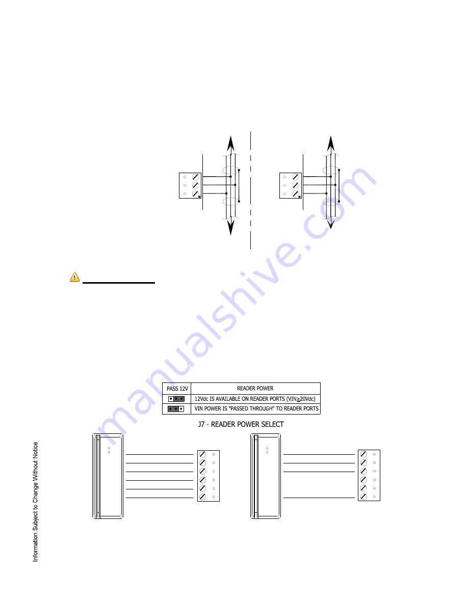
The serial I/O device communication ports, TB2 for port 1 and TB3 for port 2, are 2-wire RS-485 interface 
which can be used to connect additional I/O panels.  The interface allows multi-drop communication on a 
single  bus  of  up  to  4,000  feet  (1,219  m).    Use.  1-twisted  pair  with  drain  wire  and  shield,  120  ohm 
impedance, 24 AWG, 4,000 ft. (1,219 m) maximum for communication 


IMPORTANT  NOTE!

    Install  the  termination  jumper  ONLY  on  the  panel  at each  end  of  the  RS-485 

bus.  Failure to do so will compromise the proper operation of the communication channel! 

7.  Reader Wiring: 

Each reader port supports Wiegand, magnetic stripe, and 2-wire RS-485 electrical interfaces.  Power 
to the  reader  is  selectable:  12  Vdc  (VIN  must  be  greater  than  20  Vdc),  or  power  is  passed-through 
(PASS)  from  the  input  voltage  of  the  EP4502  (TB1-VIN)  and  is  current  limited  to  180  mA  for  each 
reader  port.    Readers  that  require  different  voltage  or  have  high  current  requirements  should  be 
powered separately.  Refer to the reader manufacture specifications for cabling requirements.  In the 
2-wire  LED  mode  the  Buzzer  output in  used  to  drive  the  second  LED.    Reader  port  configuration  is 
set via the host software.   


Data1/Data0 - Clock/Data 

Reader 

2-wire RS-485 

Device 


TR-

TR+

GND

TB3

TR-

TR+

GND

TB2

Port 1 To Serial I/O Devices

Port 2 To Serial I/O Devices

GND

DAT/D0
CLK/D1

BZR

LED

VO

TB8 OR TB9

POWER

TR+ (B)

TR- (A)

GND

GND

DAT/D0
CLK/D1

VO

TB8 OR TB9

GND
DAT/D0
CLK/D1
BUZZER

LED
POWER

Содержание EP4502

Страница 1: ...al signaling standards and also provides tri stated LED control and buzzer control one wire LED mode only Four Form C relay outputs may be used for strike control or alarm signaling The relay contacts...

Страница 2: ...NO Normally Open Contact Input 4 IN4 C Common IN4 NC Normally Closed Contact TB6 Input 5 IN5 Out 4 NO Normally Open Contact IN5 C Common Input 6 IN6 NC Normally Closed Contact IN6 TB7 Input 7 IN7 IN7...

Страница 3: ...fault parameters after OEM code has been changed Recover from database corruption causing EP4502 board to continuously reboot If clearing the memory does not correct the initialization problem contact...

Страница 4: ...the communication channel 7 Reader Wiring Each reader port supports Wiegand magnetic stripe and 2 wire RS 485 electrical interfaces Power to the reader is selectable 12 Vdc VIN must be greater than 2...

Страница 5: ...door lock mechanisms or alarm signaling The relay contacts are rated at 5 A 30 Vdc dry contact configuration Each relay has a Common pole C a Normally Open pole NO and a Normally Closed pole NC When...

Страница 6: ...tions are available to disable SNMP Zeroconf discovery as well as the web configuration module itself Additionally data encryption can also be enabled over the host communication port 12 Status LEDs P...

Страница 7: ...f this device must comply with all local fire and electrical codes Primary Power 12 to 24 Vdc 10 500 mA maximum reader current not included Memory and Clock Backup Battery 3 Volt Lithium type BR2325 B...

Страница 8: ...ury Security assumes no responsibility for products damaged by improper handling or installation This warranty is limited to the repair or replacement of the defective unit There are no expressed warr...

Отзывы: