Mcr WIP type multi-blade fire dampers
MERCOR SA –
the Company reserves the right to make modifications and changes.
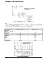
RST/KW1 release and control mechanism
In the RST/KW1/S manufacturing version, the limit switches are installed on the mechanism itself. Electrical
connection is carried out by connecting the wires (marked accordingly) to the electrica
release link is installed on the mechanism itself.
RST/KW1/S
Supply voltage
X
Power consumption
X
Holding force
X
Thermal release actuation
temperature
WK1d or WK2d limit switch
Limit switches actuation
Limit switches working temperature
Electrical connection
X
Rotation angle
Movement time
Rotation direction
Mechanism weight
1.2 kg
KW1 mechanism power supply
Wire no. 1–2
Wire no. 3
Wire no. 4
RST release and control mechanism
In the RST manufacturing version, the fusible release link is installed on the fire da
limit switches are located in the KW1 housing.
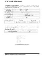
Technical data (limit switches)
WK1 and WK2 limit switches
Limit switches working temperature
Housing
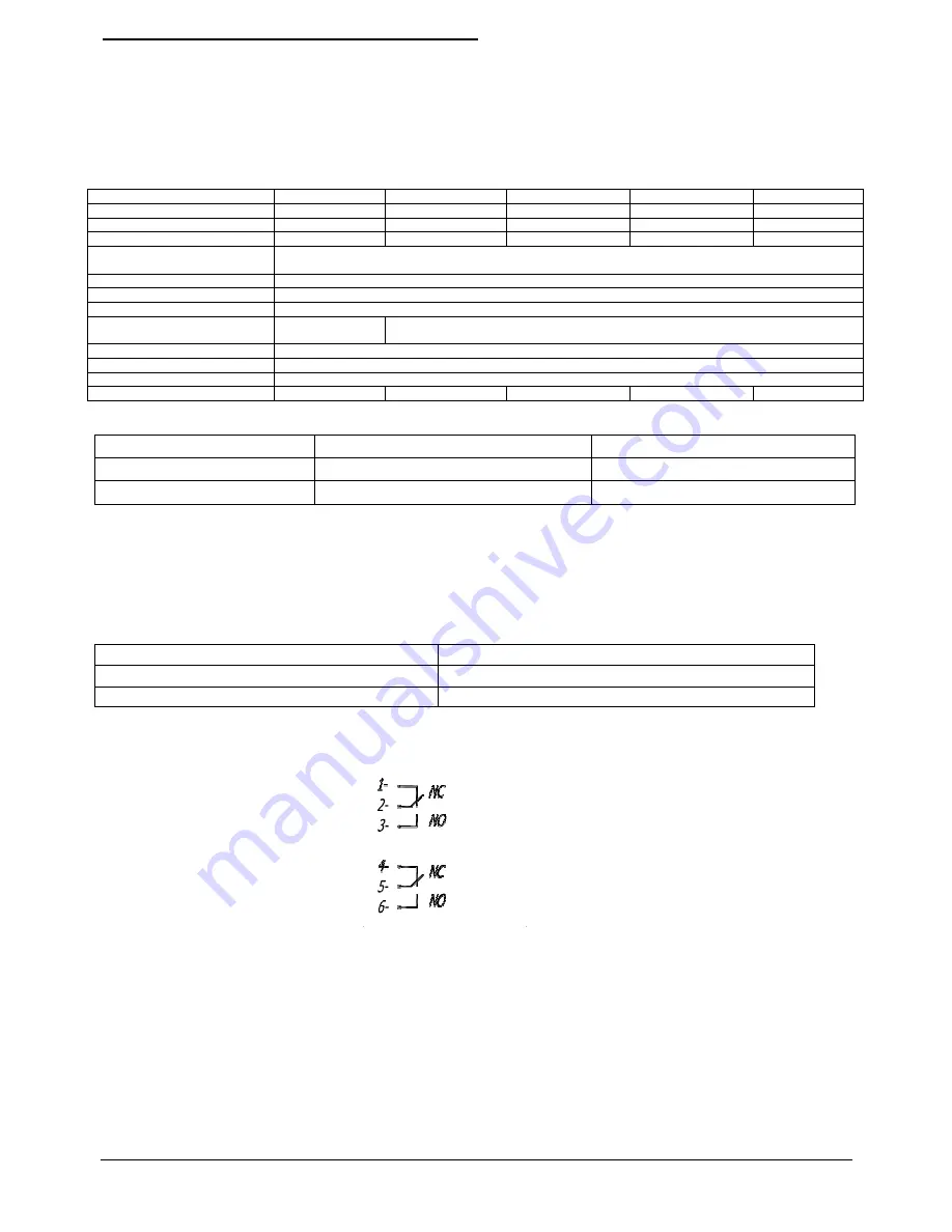
WK1 and WK2 limit switches wiring diagram
blade fire dampers
the Company reserves the right to make modifications and changes.
RST/KW1 release and control mechanism
In the RST/KW1/S manufacturing version, the limit switches are installed on the mechanism itself. Electrical
connection is carried out by connecting the wires (marked accordingly) to the electrical wiring system. The fusible
release link is installed on the mechanism itself.
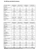
RST/KW1/S
RST/KW1/24I
RST/KW1/24P
24 V–48 V DC
24 V–48 V DC
3.5 W
1.6 W
12 daN
12 daN
72°C ±2°C
NO/NC (changeover switch) 5 A, 230 V AC
3°, 87°;
±2° tolerance
−25 ...+85°C
– release: 0.6 m cable, 2 x 0.5 mm
– limit switch: 0.6 m cable, 6 x 0.5 mm
92°
≤
2 s (spring)
left
1.4 kg
1.4 kg
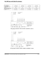
WK1 limit switch
Wire no. 3–4, NO type (normally open)
Wire no. 6
Wire no. 4–5, NC type (normally closed)
Wire no. 7
In the RST manufacturing version, the fusible release link is installed on the fire damper’s partition. Mainspring and
limit switches are located in the KW1 housing.
1 x NO/1 x NC SPDT (changeover switch) 5 A, 230 V AC
Limit switches working temperature
−25 ...+85°C
plastic
WK1 and WK2 limit switches wiring diagram
Normally open state is indicated
Normally closed state is indicated
15/17
In the RST/KW1/S manufacturing version, the limit switches are installed on the mechanism itself. Electrical
l wiring system. The fusible
NO/NC (changeover switch) 5 A, 230 V AC
release: 0.6 m cable, 2 x 0.5 mm
2
it switch: 0.6 m cable, 6 x 0.5 mm
2
WK2 limit switch
Wire no. 6-7, NO type (normally open)
Wire no. 7-8, NC type (normally closed)
mper’s partition. Mainspring and
1 x NO/1 x NC SPDT (changeover switch) 5 A, 230 V AC


