Hot Food Server Operator Manual
5
3. Install the leveling feet: Open the top drawer and remove the bag holding four 3/8” – 16 x 1” hex head cap
screws. Thread these screws hand tight into the four corner holes in the bottom of the unit (they will be
adjusted later).
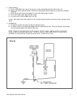
4. Electrical Connection: Built-In models are equipped with a factory installed ½” diameter x 74” flexible conduit
containing power lead pigtails and ground wire. It is necessary that this conduit and the wiring leads connect at
a junction box in accordance with your local building codes.
Important: Be sure to check the data plate on the front of the unit to be sure the power supply is correct.
5. Remove the drawer(s) from the unit by pulling the drawer out to the stop.
A. Remove
the
pan(s).
B. Grasp the entire drawer assembly at the sides as if to lift it. Locate the tabs at the front of each rail
member of the drawer slide. Press down on these tabs with your thumbs and simultaneously pull out the
drawer.
C. Set drawer assembly aside.
6. Lift the unit from both sides and slide into the cutout. Push back until the trim flange meets the face of the
cabinet.
7. Place a level on the floor of the unit and check from side to side and front to back. If adjustments are
necessary, slide the entire unit out of the cabinet and adjust the leveling feet as required. After leveling, the
unit must be secured in position. There are two holes in the unit bottom for this purpose.
8. Place a drill bit down through these two holes into the crossbrace beneath. With the screws and washers
provided, tighten a pair of sheet metal screws or wood screws (minimum 1-1/2” length) down through these
holes into the crossbrace.
9. Replace the drawers into the unit and replace the pans. The drawers of multiple drawer units are individually
identified as “top,” “2,” and “3.” They should be reinstalled in their respective position.
The unit is now installed.
INITIAL START-UP
ALL MODELS
1. Turn on the branch line circuit breaker.
2. Set the thermostat control knob at “Hi.” The pilot light will illuminate indicating that power is present.
3. Wait three (3) minutes and open the drawer(s) to see if unit is heating.
If the unit fails to heat, re-check that circuit breakers are on and electrical connections are properly made. If it still
fails to heat, call an authorized service agent.
CONTROLS
ALL MODELS
1. Control Protection: All models have control knobs and thermometers mounted in the recessed control panel for
protection.
2. Temperature Control: Temperature is controlled by a thermostat with a temperature range from 100° to 220° F.
The control panel has graduations from “OFF” to “HI.” A pilot light cycles on and off as the thermostat calls for
heat. A dial thermometer located above the temperature control knobs indicates actual holding temperature
within the Hot Food Server. To set temperature, turn the thermostat up or down for desired temperature.
3. Moisture Control: The moisture control knob is located at center front above the drawer handle. The knob
controls a sliding plate behind slots and can be adjusted over a range from fully closed to fully open. The knob
can be tightened to hold the plate in any position. This allows the operator to control the rate at which the
food’s natural moisture escapes.
Содержание HFS-1
Страница 8: ...Hot Food Server Operator Manual 8 HFS 2B HFS 3B ...
Страница 10: ...Hot Food Server Operator Manual 10 This page intentionally left blank ...
Страница 11: ...Hot Food Server Operator Manual 11 This page intentionally left blank ...
Страница 12: ...Hot Food Server Operator Manual 12 ...


