background image

8

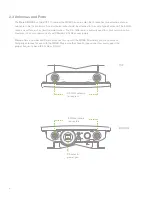
2.3  Antennas and Ports

BOTTOM

The Meraki MR66 has two 802.11n radios (the MR62 has one radio). Each radio has two external antenna 
connectors; both connectors for a particular radio should be attached to the same type of antenna. The 5 GHz 
radio is used for mesh or client communication.  The 2.4 GHz radio is primarily used for client communication. 
However, it can also communicate with Meraki 2.4 GHz access points.
 
Meraki offers a number of different antennas for use with the MR66. Alternately, you may purchase  
3rd party antennas for use with the MR66. Make sure they have N-type connectors and support the  
proper frequency band (2.4 GHz or 5 GHz).

TOP

Mount

5 GHz

5 GHz

Ethernet & 
power port

5 GHz antenna 
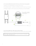
connectors

2.4 GHz

2.4 GHz

2.4 GHz antenna 
connectors

Содержание MR62

Страница 1: ...Meraki MR62 66 Hardware Installation Guide...

Страница 2: ...troller are trademarks of Meraki Inc Other brand and product names are registered trademarks or trademarks of their respective holders Warranty Meraki Inc provides a one year warranty on this product...

Страница 3: ...llect Tools 12 3 6 Collect Additional Hardware for Installation 12 4 Installation Instructions 13 4 1 Choose Your Mounting Location 13 4 2 Install the MR66 13 4 2 1 Attach the Mount Plate 14 4 2 2 1 W...

Страница 4: ...describes the installation procedure for the MR62 and MR66 access points Note All instructions in this hardware installation guide reference the MR66 but apply equally to the MR62 except where noted A...

Страница 5: ...ss 802 11n access point designed for rugged environments When connected to the Meraki Cloud Controller the MR66 enables the creation of high speed and reliable networks that cover large outdoor and in...

Страница 6: ...rior and the enviroment This prevents internal condensation and maintains a water proof seal Grounding Post Provides an attachment point on the access point for the grounding strap included This post...

Страница 7: ...on mounting strap slots 2x Horizontal orientation mounting strap slots 2x Mount plate attachment screw Mount plate ground attachment Your MR66 mount plate has the following features Mount plate attach...

Страница 8: ...nication The 2 4 GHz radio is primarily used for client communication However it can also communicate with Meraki 2 4 GHz access points Meraki offers a number of different antennas for use with the MR...

Страница 9: ...Searching for Signal Flashing Lights Error state May indicate bad gateway or other routing fault Radio Power Off MR66 is off Solid Orange MR66 is booting or trying to find a path to the internet Solid...

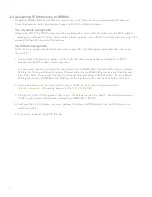
Страница 10: ...clicking and dragging it to the location where you plan to mount it You can always modify the location later 3 2 Check and Upgrade Firmware To ensure your MR66 performs optimally immediately followin...

Страница 11: ...cast by the AP or over a wired connection If using a wired connection connect the client machine to the MR66 either through a PoE switch or a Meraki PoE Injector If using a PoE switch plug an Ethernet...

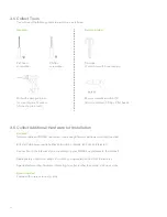
Страница 12: ...s for mounting wall anchors if mounting to a wall Required Network cables with RJ45 connectors long enough for your particular mounting location 802 3af PoE power source either PoE switch or Meraki 80...

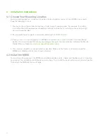
Страница 13: ...0 m 3 If being used in a mesh deployment the MR66 should have line of sight to at least two other Meraki devices For more detailed instructions regarding access point location selection reference the...

Страница 14: ...mount plate you must remove it from the back of the access point 1 Unscrew the mount plate attachment screw 2 Lift the mount plate release tab upwards 3 While holding the mount plate release tab up sl...

Страница 15: ...h the mount plate to your mounting wall or ceiling It is recommended that the MR66 be mounted to a wall or solid ceiling using the mount plate for physical security reasons 4 2 2 2 Pole Mount Using Mo...

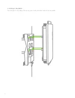
Страница 16: ...16 4 2 3 Mount the MR66 Insert the posts on the back of the access point into the attachment slots on the mount plate...

Страница 17: ...s Attach appropriate antennas and protective boots if included 4 2 3 2 Aim Antennas If you are using directional antennas aim them appropriately to ensure optimal performance for your specific network...

Страница 18: ...e Ethernet cable from the OUT port on the injector to the Ethernet port in the bay of the MR66 4 2 3 4 Powering the MR66 with an 802 3af Power over Ethernet Switch Route Ethernet cable from a port on...

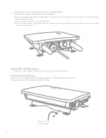
Страница 19: ...o the MR66 2 Route the Ethernet cable from the PoE Injector OUT port to the MR66 3 Install a Cable Gland on the MR66 end of the cable 1 Remove the dust cover from the Ethernet port of the MR66 Unscrew...

Страница 20: ...lit ring gasket into the gland body d Screw the cap tightly onto the gland You may need a wrench to fully tighten the cap but take care not to damage the cable in the process Connect to metal structur...

Страница 21: ...will show the signal strength to the nearest Meraki device See section 2 6 for further details about information conveyed by the LEDs Note Your MR66 must have an active route to the Internet to check...

Страница 22: ...CIRCUIT DIFFERENT FROM that to which the receiver is connected s ONSULT THE DEALER OR AN EXPERIENCED RADIO 46 TECHNICIAN FOR HELP FCC Caution Any changes or modifications not expressly approved by th...

Страница 23: ...irements of the R TTE Directive 1999 5 EC The following test methods have been applied in order to prove presumption of conformity with the essential requirements of the R TTE Directive 1999 5 EC Radi...

Страница 24: ...UDNL QF GHFODUHV WKDW WKLV ZLUHOHVV GHYLFH LV LQ FRPSOLDQFH ZLWK WKH HVVHQWLDO UHTXLUHPHQWV DQG RWKHU UHOHYDQW SURYLVLRQV RI LUHFWLYH VSDxRO 6SDQLVK 3RU PHGLR GH OD SUHVHQWH 0HUDNL QF GHFODUD TXH HO Z...

Страница 25: ...QF R ZLDGF D H ZLUHOHVV GHYLFH MHVW JRGQ DVDGQLF PL Z PRJDPL RUD SR RVWDO PL VWRVRZQ PL 3RUWXJXrV 3RUWXJXHVH 0HUDNL QF GHFODUD TXH HVWH ZLUHOHVV GHYLFH HVWi FRQIRUPH FRP RV UHTXLVLWRV HVVHQFLDLV H RX...

Страница 26: ...ted s ONSULT THE DEALER OR AN EXPERIENCED RADIO 46 TECHNICIAN FOR HELP FCC Caution Any changes or modifications not expressly approved by the party responsible for compliance could void the user s aut...

Страница 27: ...een applied in order to prove presumption of conformity with the essential requirements of the R TTE Directive 1999 5 EC Radio EN 300 328 EN 301 893 EMC EN 301 489 1 EN 301 489 17 Safety EN 60950 1 RF...

Страница 28: ...UDNL QF GHFODUHV WKDW WKLV ZLUHOHVV GHYLFH LV LQ FRPSOLDQFH ZLWK WKH HVVHQWLDO UHTXLUHPHQWV DQG RWKHU UHOHYDQW SURYLVLRQV RI LUHFWLYH VSDxRO 6SDQLVK 3RU PHGLR GH OD SUHVHQWH 0HUDNL QF GHFODUD TXH HO Z...

Страница 29: ...QF R ZLDGF D H ZLUHOHVV GHYLFH MHVW JRGQ DVDGQLF PL Z PRJDPL RUD SR RVWDO PL VWRVRZQ PL 3RUWXJXrV 3RUWXJXHVH 0HUDNL QF GHFODUD TXH HVWH ZLUHOHVV GHYLFH HVWi FRQIRUPH FRP RV UHTXLVLWRV HVVHQFLDLV H RX...

Страница 30: ...30 Copyright 2011 Meraki Inc All rights reserved Trademarks Meraki is a registered trademark of Meraki Inc...

Страница 31: ...31 www meraki com 660 Alabama St San Francisco California 94110 Phone 1 415 632 5800 Fax 1 415 632 5890...

Страница 32: ...Meraki Inc 2011 280 09100 A...

Отзывы: