


Installation
Rev 1.2
Mellanox Technologies
21
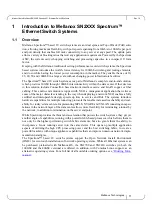
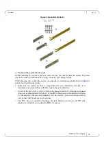
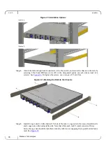
Figure 9: Attaching the Brackets to the Chassis
Step 4.
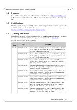
Install 8 cage nuts in the desired 1U slots of the rack: 4 cage nuts in the non-extractable side (in
the top and bottom holes only) and 4 cage nuts in the extractable side.
Figure 10: Installing the Cage Nuts
While your installation partner is supporting the system’s weight, perform the following steps:
Step 5.
Mount the system into the rack enclosure, and attach the brackets installed on the system to the
rack’s posts. Secure the brackets to the rack’s posts by inserting four M6 screws in the desig-
nated cage nuts, as described in
. Do not tighten the screws yet.
While each rack U (unit) consists of three holes, the cage nut should be installed verti-
cally with its ears engaging the top and bottom holes only.
Содержание Spectrum SN2410
Страница 1: ...www mellanox com Mellanox 1U Switch Systems Hardware User Manual Models SN2700 and SN2410 Rev 1 2...
Страница 53: ...Interfaces Rev 1 2 Mellanox Technologies 53 Figure 45 SN2410 Inventory Information Illustration...
Страница 72: ...Mellanox Technologies 72 8 9 10 11 12 13...
Страница 73: ...Rev 1 2 Mellanox Technologies 73 14 15 16 17 18 19...
Страница 75: ...Rev 1 2 Mellanox Technologies 75 3 4 5 6 7 8 9 45 C 113 F 8 3 PSU...
Страница 76: ...Mellanox Technologies 76 10 11 12 13 14 15 16 UL 4mA...
Страница 78: ...Mellanox Technologies 78 23 24 China CCC Warning Statement TN IT...
Страница 91: ...Rev 1 2 Mellanox Technologies 91 7 8 9 10 11 12 13...
Страница 92: ...Mellanox Technologies 92 14 15 16 17 18 UL CSA 19 UL 4 UL CSA 3 16 AWG 1 5 6 4 5 125 13 HAR 3 1 0 300 250 10...


