


Interfaces
Rev 1.0
20
Mellanox Technologies
3.4
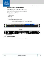
ConnectX®-4 QSFP Ports
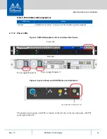
These 2 QSFP ports are found on the rear side of the appliance. See Figure 13. They should be
connected to an IB switch in the fabric, it is recommended to connect to two different switches
for redundancy. The appliance can be connected only to a single IB fabric.
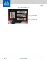
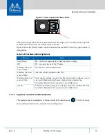
3.4.1 QSFP Port Interfaces
There is one I/O LED per port. See Table 8 below for LED functionality in InfiniBand mode.
Figure 14: Illustration of InfiniBand Port Connector Interfaces
3.5
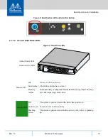
RJ-45 Ethernet Connector for Remote Management
The appliance has multiple Ethernet management interfaces. The primary management interface
is eth0. An additional interface exists, for connecting to a remote management controller (It usu-
ally connects to the same management network as eth0). For using out-of-the-box DHCP set-
tings: Default hostname for the appliance (over eth0) is “ufm-appliance-[MAC ADDRESS]”.
The MAC address for eth0 is available on the pull-tab and can be configured in the DHCP server.
To use the remote management controller with DHCP, the free-range IP allocation must be
enabled on the DHCP server. A static IP address for remote management interface can be config-
ured via the CLI (“chassis remote-management ip” command).
Table 8 - Physical and Logical Link Indication
LED
Function
Off
Physical link has not been established.
Solid Yellow
Indicates an active physical link.
Blinking Yellow
Indicates a problem with the physical link.
Solid Green
Indicates a valid logical (data activity) link with no active traffic.
Blinking Green
Indicates a valid logical link with active traffic.


