background image

Rev 2.0.0

Mellanox Technologies 

8

2

Installation and Basic Operation

2.1 Switch Platform Hardware Overview

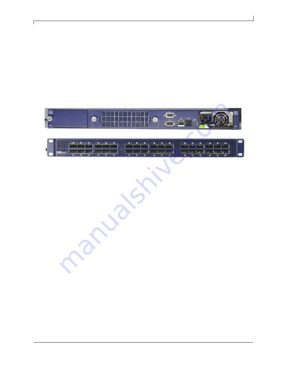
Figure 3 shows the power side panel and connector side panel views of the QSFP switch. The figure shows 
port configurations for the switch systems, including the dual hot-swap power supplies, and hot-swap fan 
module, I2C connector, RJ45 connector, USB connectors, VGA port connector, and various status LEDs. 

Figure 3: QSFP Switch System Front and Back Panels    

All InfiniBand connectivity is via the connector side panel. All connectors can support active cables. 

2.1.1 Status LEDs

2.1.1.1 System Status Indicators

The System Status Indicators are located just to the left of the primary power supply unit, and labeled “Sys.”. 

The system status indicators should be as follows:

Œ

When the switch is plugged in, within a few seconds the STATUS LED should light up green.

Œ

The PSU 1 LED should light up green. 

Œ

The PSU 2 LED should light up green only if a second PSU is installed in the switch for redundancy 
and Hot-Swap ability. If only one PSU is installed in the switch, the PSU 2 LED will be off. 

Œ

The FAN LED should light up green. 

If the STATUS LED shows red unplug the switch and call your Mellanox representative for assistance.

If the FAN LED shows yellow, trouble shoot the fan module.

Note: Do not run the switch for more than 2 minutes should the FAN LED show yellow.

If the PSU LEDs are not green, this indicates a problem with the power supplies. Do not run the switch if the 
PSU LEDs are not green. 

Front panel

Rear panel

Содержание InfiniScale MTS3600Q-1BNC

Страница 1: ...lanox Technologies InfiniScale IV 36 Port QSFP InfiniBand Switch User Manual P N MTS3600Q 1BNC MTS3600Q 2BNC MTS3600Q 1UNC MTS3600Q 2UNC MTS3600R 1BNC MTS3600R 2BNC MTS3600R 1UNC MTS3600R 2UNC Rev 2 0...

Страница 2: ...SOLELY FOR THE PURPOSE OF AIDING THE CUSTOMER IN TEST ING APPLICATIONS THAT USE THE PRODUCTS IN DESIGNATED SOLUTIONS THE CUS TOMER S MANUFACTURING TEST ENVIRONMENT HAS NOT MET THE STANDARDS SET BY MEL...

Страница 3: ...erting the Power Supply Unit 17 2 2 5 InfiniBand Cable Installation 18 2 2 6 Extracting and Inserting the Fan Unit 19 2 2 7 Replacing the Battery in the Management Module 20 2 3 Disassembly of the Swi...

Страница 4: ...Fabric IT section April 2009 Rev 1 7 inserted procedure to replace the battery April 2009 Rev 1 6 Changes to installation kit and procedure January 2009 Rev 1 5 added installation instructions added E...

Страница 5: ...Update Tools See http www mellanox com Downloads Firmware Tools Note that the Switch System described in this manual is based on Mellanox Technologies InfiniScale IV switch device Mellanox OFED Stack...

Страница 6: ...port Unmanaged QSFP 40Gb s InfiniBand switch with two power supplies MTS3600R 1UNC 36 port Unmanaged QSFP 20Gb s InfiniBand switch with one power supply MTS3600R 2UNC 36 port Unmanaged QSFP 20Gb s Inf...

Страница 7: ...iBand fabric This switch requires an InfiniBand compliant Subnet Manager running from one of the hosts All that is required for normal operation is to follow the usual precautions for installation and...

Страница 8: ...t to the left of the primary power supply unit and labeled Sys The system status indicators should be as follows When the switch is plugged in within a few seconds the STATUS LED should light up green...

Страница 9: ...nit installed a second Power Supply Unit can be added to increase security hot swap ability and to add redundancy Figure 5 MTS3600 QSFP Front Panel LED Configuration Status OK The system is up and run...

Страница 10: ...ollowing fan status conditions are possible Table 6 Fan Status LED Configurations 2 1 2 I2 C Connector The MTS3600 supports an I2C compatible interface on the front panel This interface is used to pro...

Страница 11: ...ement operation 2 2 Switch Platform Installation and Operation Installation and initialization of the switch platform are straightforward processes requiring attention to the normal mechanical power a...

Страница 12: ...nce around the ventilation openings The chassis should not be stacked on any other equipment If the chassis falls it can cause bodily injury and equipment damage This product includes a blank cover ov...

Страница 13: ...should use a rack capable of supporting the mechanical and environmental characteristics of a fully populated platform 2 2 2 1 Installing the Switch in the Rack Tools needed Phillips Screwdriver ESD S...

Страница 14: ...ace the ESD mat on the floor where you will be working and put on the ESD strap Make sure the ESD strap is touching your skin and that the other end is connected to a verified ground 2 Choose which si...

Страница 15: ...itch that you want to be even with the vertical support of the 19 rack Use four of the flat head screws for each rail slide There are two sets of holes in the rail slide Select the set of holes to eit...

Страница 16: ...within reach 7 Slide the switch into the rails 8 Put the switch into place and screw the bolts into the nuts from step 4 Tighten the bolts to 9 2 Nm or 81 5 pound inches 9 Tighten all of the screws 10...

Страница 17: ...y modules for proper insertion before plugging in a power cable Caution After inserting a power cable and confirming the green system status LED light is on make sure that the Fan Status indicator sho...

Страница 18: ...the power cord into the supply connector Note The green PSU indicator should light and the yellow indicator should remain off If not extract the PSU and re insert it 2 2 5 InfiniBand Cable Installatio...

Страница 19: ...re bending upward or downward in the rack Figure 13 Cable connections to the Switch 2 2 6 Extracting and Inserting the Fan Unit This switch can operate indefinitely with one of the three fans in the f...

Страница 20: ...m the rack 3 Put on an ESD strap and ground the strap to a valid ground 4 Remove the rail slides from the switch Put aside the rail slides and screws for later use 5 Remove the cover from the switch a...

Страница 21: ...he eight caged nuts 2 4 Disposal According to the WEEE Directive 2002 96 EC all waste electrical and elec tronic equipment EEE should be collected separately and not disposed of with regular household...

Страница 22: ...odule The management module for this switch system runs SW that can manage the chassis An option to upgrade the management module to be able to manage the whole fabric is available See your Mellanox r...

Страница 23: ...r an RJ45 connector on the host PC side 3 2 2 2 Accessing the CPU via Keyboard Video Mouse KVM 1 Connect a keyboard to the one of the USB ports a video device to the video connector and a mouse to the...

Страница 24: ...re robust and can manage a whole fabric 4 1 FabricIT FabricIT EFM is a software based management system that can be run with either a command line interface or with a GUI interface The GUI interface c...

Страница 25: ...n the PSU Unit is on 3 Remove and reinstall the power cable Check that the power outlet in the wall is working 4 Remove and reinstall the PSU Make sure the mating connector of the new unit is free of...

Страница 26: ...ure that the latest FW version is installed on both the HCA and the switch 4 If media adapters are used check that the all connections are good tight and secure The activity LED does not come on Check...

Страница 27: ...ion of 40Gb s 20Gb s 10Gb s 8 InfiniBand Virtual Lanes for all ports Baseboard Performance and Device man agement Agents for full InfiniBand In Band Management QDR Safety EMC Emissions Environmental A...

Страница 28: ...tual Lanes for all ports Baseboard Performance and Device man agement Agents for full InfiniBand In Band Management DDR Safety EMC Emissions Environmental Acoustic Sound power level US Canada cTUVus E...

Страница 29: ...digital device pursuant to Part 15 of the FCC Rules These limits are designed to provide reasonable protection against harmful interference when the equipment is operated in a commercial environment T...

Страница 30: ...Japan Class A Statement 0 0 1 Translation This is a Class A product based on the standard of the Voluntary Control Council for Interference by Information Technology Equipment VCCI If this equipment...

Страница 31: ...Scale IV 36 Port QSFP InfiniBand Switch User Manual MellanoxTechnologies Rev 2 0 0 31 Appendix B Switch Hardware Components Fan Unit Primary Power Supply Unit Place for Optional Secondary Power Supply...

Страница 32: ...etL Module Reset 10 Vcc Rx 3 3 V Power supply receiver 11 SCL 2 wire serial interface clock 12 SDA 2 wire serial interface data 13 GND Ground 14 Rx3p Receiver Non Inverted Data Output 15 Rx3n Receiver...

Страница 33: ...Unit for QSFP MTF000960 Management module 405 PPC SA000102 Management module upgrade to 460 PPC SA000102 RS232 CABLE DB9 TO DB9 HARNESS HAR000040 Power cord Type B for USA Canada Mexico Taiwan ACC000...

Страница 34: ...ch ssis ne doit pas tre empil sur un autre mat riel Si le ch ssis tombe il peut pro voquer des blessures corporelles et des d gradations de biens Ce produit comporte un couvercle transparent sur l esp...

Страница 35: ...10 Codes lectriques locaux et nationaux Ce mat riel ne doit tre install remplac ou entretenu que par du personnel form et qualifi L limination de ce mat riel doit s effectuer dans le respect de toutes...

Страница 36: ...Chassis sollte nicht auf andere Ger te gestapelt werden Wenn das Chassis herunt erf llt kann es zu Verletzungen und Besch digungen an Ger ten f hren Dieses Produkt verf gt ber eine Abdeckung ber dem...

Страница 37: ...nale elektrische Bestimmungen Diese Ger t sollte nur von geschultem und qualifiziertem Personal installiert ausge tauscht oder gewartet werden Die Entsorgung dieses Ger ts sollte unter Beachtung aller...

Страница 38: ...n Denmark The AC cord shall have an integral ground wire and can only be plugged into a fully grounded outlet Finland Norway Sweden Do not connect this unit to any outlet that is not fully grounded La...

Отзывы: