9
Serial Port
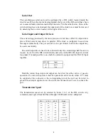
The asynchronous serial port can be configured by a DIL switch located inside the
clock's case. When the clock is beeing shipped, the levers of the DIL switch have been
set to some defaults which are marked by asterisks (*) in the tables below. If one of the
switch settings has to be changed, the upper part of the clock's case must be removed
by detaching the 4 screws located at the edges of the cover.
Serial Input and Output Drivers
The serial string generated by the microprocessor is fed into a RS-232 output driver
plus a 20mA current loop driver in parallel. If the clock is configured to send time
messages automatically once per second or once per minute, both of the outputs may
be used concurrently.
The serial input drivers need to be connected only if a serial string shall be sent on
request. Lever 10 of the DIL switch lets the user select either RS-232 input or current
loop input. It is not possible to use both the current loop input and the RS-232 input
together.
SW1-10
Input
off
RS232
*
on
20mA
Both the current loop input and output can be wired for either active or passive
operation. If a current loop driver shall be operated in active mode, either -15V must
be supplied at the connector or the corresponding pin of the port can be wired to
ground An example application at the end of this manual shows how to connect the
port.
Transmission Speed
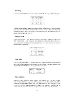
The transmission speed can by selected by levers 1 to 3 of the DIL switch. Any
commonly used speed from 600 baud through 19200 baud can be configured:
S W - 1
S W - 2
S W - 3
B a u d
on
on
on
600
off
on
on
1200
on
off
on
2400
off
off
on
4800
on
on
off
9600
*
off
on
off
19200
on
off
off
( r e s e r v e d )
off
off
off
( r e s e r v e d )
Содержание DCF77C51
Страница 1: ...DCF77C51 Technical Information Operating Instructions FUNKUHREN...
Страница 4: ......
Страница 6: ...6...
Страница 16: ...16...
Страница 17: ...17 Component Layout...
Страница 20: ......


