background image

Page 24 


Insulation measurements above 100 G

Ω


Measurements up to 100 G

Ω

 can be made without any special 

precautions, assuming that the test leads are reasonably clean 
and dry. The guard lead can be used to remove the effects of 
surface leakage if necessary. When measuring resistances above 
100 G

Ω

, the test leads should not be allowed to touch each other, 

or any other object since this will introduce leakage paths. Sharp 
points at the test lead connections should also be avoided since 
this will encourage corona discharge.  
 
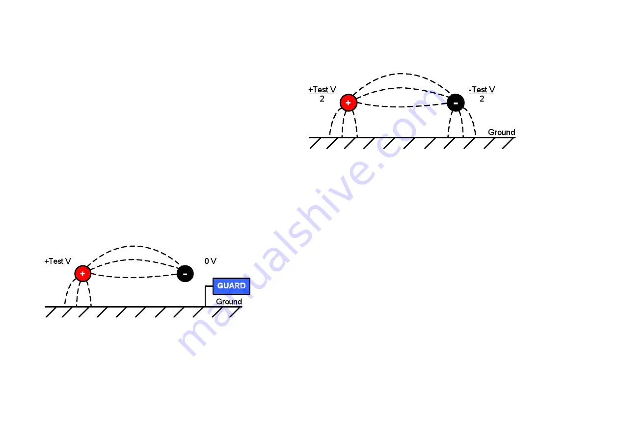
The output is isolated, and so will float relative to ground such 
that the positive terminal is at plus half of the test voltage, and the 
negative terminal is at minus half of the test voltage with respect 
to ground. 
 
Leakages therefore occur between the positive terminal and 
ground, between the negative terminal and ground, and directly 
between the positive and negative terminals. These leakages 
have a significant effect and can occur through air. 


If the guard lead is grounded, and since the negative terminal is 
at the same voltage as the guard terminal, the leakage into the 
negative terminal will be considerably reduced. This will improve 
accuracy because the current flowing into the negative terminal is 
measured by the instrument and used to calculate resistance. 
This technique is only permissible if the item under test is isolated 
from ground. In this context 

isolated

 means insulated by a 

resistance of at least 5 M

Ω

 for the positive terminal, or at least  

10 k

Ω

 for the negative terminal. 


Conversely, if the positive terminal is grounded, then the negative 
terminal will be at a voltage equal to the test voltage relative to 
ground, which will result in an increase in leakage current, and 
worsening of measurement accuracy. 
 
When making measurements above 100 G

Ω

 therefore, the user 

should ground the Guard lead where possible otherwise parallel 
leakage paths may occur. 
 
Alternatively, screened leads are available as an optional accessory 
from Megger. When using a screened lead the screen is plugged 
into the Guard terminal, diverting any leakage currents. This 
considerably improves measurements made with a floating output, 
where the leads might touch each other or another object other than 
the test piece.  

Terminals 

There are three test terminals , - and GUARD. These 
terminals are designed to accept only genuine Megger test leads. 
Shutters across the terminals prevent accidental ingress of dirt and 
other objects. Test lead plugs interlock with the shutters and are 
released by rotating the test lead plug by a quarter turn. 
 
The GUARD terminal, as explained below, is only used in cases 
where surface leakage currents need to be eliminated. Most 

Содержание S1-1068

Страница 1: ...S1 568 S1 1068 S1 1568 5 kV 10 kV 15 kV High Performance DC Insulation Resistance Testers USER MANUAL M...

Страница 2: ...navoidable the user must take all necessary precautions This instrument is not intrinsically safe and must not be used in hazardous atmospheres If this equipment is used in a manner not specified by t...

Страница 3: ...Directive The crossed out wheeled bin symbol on the instrument and on the batteries is a reminder not to dispose of them with general waste at the end of their life Megger is registered in the UK as...

Страница 4: ...ime output during insulation tests 13 Bluetooth interface activation 14 PowerDB 15 Interfacing S1 and MIT ranges to PowerDB 15 Battery indicator 18 On screen error reporting 18 Error codes 18 Measurem...

Страница 5: ...tions ensure highest quality resistance measurements All models support diagnostic and over voltage tests PI DAR DD SV and ramp test Remote Control RC mode via USB cable Bluetooth link for live stream...

Страница 6: ...h associated HV warning lamp 8 Backlight button 9 Range rotary switch 10 Save button 11 Test mode rotary switch 12 LED indicating line power mains 13 Filter button 14 Display 15 Power socket 16 Functi...

Страница 7: ...265 V rms ac at 50 60 Hz A green LED illuminates when line power mains is present The battery will charge over its operating temperature range as long as an AC source is connected except when a test...

Страница 8: ...all models have a backlight button The mode rotary switch controls the insulation test type Basic insulation resistance IR timed insulation resistance IR t Dielectric Absorption Ratio DAR Polarisation...

Страница 9: ...To test for high noise select the voltmeter function and read the voltage A high voltage will indicate a high noise environment Voltmeter A voltmeter is incorporated in the instrument and measures AC...

Страница 10: ...istance of an insulator reaches this limit The default alarm setting is 500 k and inactive x is displayed on the right of the display Set range and mode switches to the settings and IR positions respe...

Страница 11: ...etection and test voltage continues after breakdown of the insulation This enables the location of a failure to be detected but it is a destructive test Due to the potential damage that could occur th...

Страница 12: ...is complete The save icon will appear momentarily to confirm the data is saved If a full test curve is required the user must select logging by pressing the save button before starting the test In th...

Страница 13: ...er exists use it when starting PowerDB for the first time to find the S1 driver if not allow the operating system to search the internet for the driver When using the USB cable check the serial port a...

Страница 14: ...on the S1 and the PC Let the PC find the S1 its serial number will be part of the identifier and default passcode for connection is 0000 Create a connection to the S1 and check the link works by conn...

Страница 15: ...the version supplied on the product CD if the PC being used has no access to the internet The instrument does not need to be powered up to respond to the driver as it is powered via the USB cable Load...

Страница 16: ...itialise the instrument An OK confirmation appears at the top of the form if communications have been successful Scroll down the PowerDB form until you see a table with cyan filled headers RIGHT CLICK...

Страница 17: ...hree tables are available in the PowerDB form representing three phases named A B and C Tests listed in the Import Live Stream Control application listed under Test Info can be saved in any form by ex...

Страница 18: ...the battery has failed On screen error reporting Should an error be detected during the operation of the S1 instrument an error code is reported preceded by Err with the read handbook warning Error co...

Страница 19: ...is calculated and displayed Time Constant TC Rinsulation x Cinsulation Timed IR test A timed test IR t will automatically terminate an insulation test after a preset time Default timer is set to 1 mi...

Страница 20: ...developed by EDF France s power utility company it is a diagnostic insulation test that allows ageing deterioration and voids in the insulation to be assessed The result is dependent on the discharge...

Страница 21: ...required at the VL voltage set timer 1 to 0 sec if a custom SV test has previously been setup Rotary switch setting indicated For a regular 5 step SV test resistance readings for the first four steps...

Страница 22: ...kV is recorded and can be read into PowerDB PowerDB Lite or converted to a spreadsheet so that the current vs voltage curves can be compared to published curves in IEEE 95 2002 Remote control mode Rem...

Страница 23: ...total current has four components capacitive current absorption current conductance current and leakage current If a generator has wet or contaminated windings conductance current will be present In...

Страница 24: ...red by the instrument and used to calculate resistance This technique is only permissible if the item under test is isolated from ground In this context isolated means insulated by a resistance of at...

Страница 25: ...same potential as the negative terminal Since the leakage resistance is effectively in parallel with the resistance to be measured the use of the guard causes the current flowing through surface leak...

Страница 26: ...nd all other equipment before opening the case to change the battery The instrument must not be operated with the case open DANGER Hazardous voltages are exposed with the mains connected and the case...

Страница 27: ...hange the battery 2 Always replace both battery packs together 3 The instrument must not be operated with the case open DANGER Hazardous voltages are exposed with an AC source connected and the case o...

Страница 28: ...1068 10 k to 35 T S1 1568 10 k to 35 T Accuracy 23 C S1 568 5000 V 2500 V 1000 V 500 V 250 V 5 to 1 T 500 G 200 G 100 G 50 G 20 to 10 T 5 T 2 T 1 T 500 G S1 1068 10000 V 5000 V 2500 V 1000 V 500 V 5 t...

Страница 29: ...z 65 Hz Timer range 99 m 59 s 15 s minimum setting Memory capacity 11 hrs logging 5 sec intervals Test regimes IR IR t DAR PI SV DD ramp test Interfaces USB type B device Bluetooth Real time output re...

Страница 30: ...8579 Fax 1 610 676 8625 Megger operate fully traceable calibration and repair facilities ensuring your instrument continues to provide the high standard of performance and workmanship you expect These...

Страница 31: ...Page 31 Approved Service Centres A list of Approved Service Centres may be obtained from the UK address above or by contacting Megger on ukrepairs megger com and giving details of your location...

Страница 32: ...dium insulated clips 1002 531 Shielded USB cable PowerDB Lite software CD Remote control indicator dongle S1 1068 only 3 m leadset x 3 large insulated clips 1002 534 S1 1568 only 3 m 15 kV leadset x 3...

Страница 33: ...S France T 33 0 1 30 16 08 90 F 33 0 1 34 61 23 77 E infos megger com Megger AB Box 724 182 17 Danderyd Sweden T 46 8 510 195 00 F 46 8 510 195 95 Megger Pty limited Unit 1 11 21 Underwood Road Homebu...

Отзывы: