background image

If the power lead supplied is not suitable for your type of mains outlet, do

not use an adaptor. Always use a power lead fitted with the correct plug. 

NB

: A plug severed from the power lead is a hazard if plugged into a live

socket. Severed plugs must be destroyed immediately.

The instrument is fitted with a two-pin IEC60320 power inlet. Most power

leads are made with three-core cable so the ground connection will not

be used. 

Power lead cable colour coding:

International

USA

Earth/Ground

Yellow/Green

Green

Neutral

Blue

White

Live (Line)

Brown

Black

If using a fused plug ensure it is fitted with a 3 Amp fuse.

The instrument can be powered from 95 - 240 V rms, ±10% 50/60Hz.

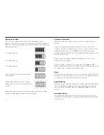
With power connected the battery will charge as long as a test is not in

progress. The 

Power On/Off

button has a green LED which illuminates

when mains power is present. 

For best battery lifetime, charge the battery after each use. A completely

exhausted battery will take 14 hours to recharge.  

INTRODUCTION

POWER LEAD AND CHARGING

4

The MIT510 is a compact microprocessor controlled high voltage d.c.

insulation tester, powered by internal rechargeable battery or mains

supply. A comprehensive LCD display shows resistance, current,

capacitance, voltage and timer measurements digitally, with resistance

being shown in analogue as well.

Features include:

Resistance or current measurement- front panel selectable

Resistance measurement range - 10 k

to 15 T

Front panel selectable test voltages - 250 V, 500 V, 1000 V, 2500 V, 5000 V

Incremental timer (minutes & seconds) – measures during test

Load capacitance measurement – displayed at end of a test

LCD backlight – front panel selectable

Battery level/charging indicator

Mains (line) input presence LED

High voltage warning flashing LED shows when greater than 50 V

present on test leads

High voltage warning LCD "flash" shows when greater than 50 V 

present on test leads

8 hours continuous testing on full charge.

Содержание MIT510

Страница 1: ...M MIT510 5kV Digital Insulation Tester USER MANUAL...

Страница 2: ...ces breakdown of the circuit under test may cause a loss of display presence of HV on the test leads will still be shown by a flashing red LED If this happens stop the test immediately by pressing the...

Страница 3: ...r lead and charging the batteries 4 Quick start 5 Instrument controls and indicators 6 Power On Off button 6 V and V buttons 6 Test button 6 I button 6 B button 7 HV On LED 7 Charging indicator LED 7...

Страница 4: ...y lifetime charge the battery after each use A completely exhausted battery will take 14 hours to recharge INTRODUCTION POWER LEAD AND CHARGING 4 The MIT510 is a compact microprocessor controlled high...

Страница 5: ...orm a self check during which Ini is displayed After Ini disappears the instrument is ready for use 3 Check voltage at terminals display to be sure the load is safe to energise 4 Set test voltage requ...

Страница 6: ...nly If the test voltage is changed during a test the new test voltage will be displayed briefly before the display again shows the voltage on the test leads After a test has been stopped the display s...

Страница 7: ...voltage greater than 50 V from an internal or external source on the test inputs the LED flashes Charging Indicator LED This is a green LED next to the Power On Off button on the front panel When main...

Страница 8: ...f the last test remains on the display until another test is started Digital Display The digital display shows the resistance or current being measured during a test The I button toggles between the t...

Страница 9: ...d Voltage input range 85 260 V 50 60Hz Battery life 6 hours continuous testing at 5 kV Test voltages 250 V 500 V 1000 V 2500 V 5000 V Accuracy 23 C 5 to 1 T 15 1 T to 7 5 T 20 5 T to 10 T 5 counts Gua...

Страница 10: ...ominal test voltage at 100 M load Current measurement range 0 01 nA to 5 mA Current measurement accuracy 23 C 5 0 2 nA at all voltages Display Analogue Digital 3 digits Interference rejection 2mA rms...

Страница 11: ...ncluded Accessories 3m lead set 8101 181 User guide on CD ROM 6172 929 Optional Accessories 3m lead set with straight jaw clamps 6220 797 15m lead set 8101 183 3m lead set insulated clamps Contact Meg...

Страница 12: ...rument for Repair If it is necessary to retun an instrument for repair a returns Authorisation number must first be obtained by contacting one of the addresses shown You will be asked to provide key i...

Страница 13: ......

Страница 14: ...er com Megger Pty Limited Unit 26 9 Hudson Avenue Castle Hill Sydney NSW 2125 Australia T 61 0 2 9659 2005 F 61 0 2 9659 2201 E ausales megger com Megger Limited 110 Milner Avenue Unit 1 Scarborough O...

Отзывы: