background image

INSTRUMENT CONTROLS AND INDICATORS

Power On/Off button:

The instrument will only turn on if this button is pressed, held and then

released after the display responds. 

If pressed and released before the display responds the instrument will

not turn on. 

If pressed and held continuously the instrument will not turn on.

This sequence is a safety feature to prevent the instrument inadvertently

turning on. 

To power the instrument down at any time, press 

Power On/Off

again.

The instrument will also power down after 10 minutes of inactivity.

Once powered, the display will first show 

Ini

while it does a self-check.

When 

Ini

disappears, the instrument is ready for use.

V

and V

buttons:

Using these buttons one of five test voltages can be selected: 250 V, 

500 V, 1000 V, 2500 V or 5000 V. The selected voltage is shown on the

display.

If there is an external voltage greater than 50 V on the test leads the

display will show this voltage instead. The instrument will not do a test if

this is the case.

After a test has started, the display shows the voltage on the test leads

only. If the test voltage is changed during a test, the new test voltage will

be displayed briefly before the display again shows the voltage on the test

leads.

After a test has been stopped, the display shows the test voltage selected

once the load has discharged to below 50 V.

TEST button:

A test will only start if this button is pressed, held and then released as

soon as the red HV LED lights. When the test starts the red HV LED flashes

and the display flashes the HV warning symbols.

If pressed and released before red LED shows a test will not start. 

If pressed and held continuously the instrument will immediately stop the

test.

This sequence is a safety feature to prevent the instrument inadvertently

starting a test. 

If an external voltage greater than 50 V is present on the test leads, this

will be shown by the red HV LED and the display HV warning symbols

flashing. Testing will be disabled until this voltage falls below 50 V.

Testing will stop if the 

TEST

button is pressed again.

After a test has finished, the instrument will discharge the load which may

take some time. Always check the load has been discharged before

touching the test leads.

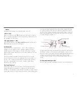
/I button:

Pressing this button toggles the digital display between the insulation

resistance and current. 

6

Содержание MIT510

Страница 1: ...M MIT510 5kV Digital Insulation Tester USER MANUAL...

Страница 2: ...ces breakdown of the circuit under test may cause a loss of display presence of HV on the test leads will still be shown by a flashing red LED If this happens stop the test immediately by pressing the...

Страница 3: ...r lead and charging the batteries 4 Quick start 5 Instrument controls and indicators 6 Power On Off button 6 V and V buttons 6 Test button 6 I button 6 B button 7 HV On LED 7 Charging indicator LED 7...

Страница 4: ...y lifetime charge the battery after each use A completely exhausted battery will take 14 hours to recharge INTRODUCTION POWER LEAD AND CHARGING 4 The MIT510 is a compact microprocessor controlled high...

Страница 5: ...orm a self check during which Ini is displayed After Ini disappears the instrument is ready for use 3 Check voltage at terminals display to be sure the load is safe to energise 4 Set test voltage requ...

Страница 6: ...nly If the test voltage is changed during a test the new test voltage will be displayed briefly before the display again shows the voltage on the test leads After a test has been stopped the display s...

Страница 7: ...voltage greater than 50 V from an internal or external source on the test inputs the LED flashes Charging Indicator LED This is a green LED next to the Power On Off button on the front panel When main...

Страница 8: ...f the last test remains on the display until another test is started Digital Display The digital display shows the resistance or current being measured during a test The I button toggles between the t...

Страница 9: ...d Voltage input range 85 260 V 50 60Hz Battery life 6 hours continuous testing at 5 kV Test voltages 250 V 500 V 1000 V 2500 V 5000 V Accuracy 23 C 5 to 1 T 15 1 T to 7 5 T 20 5 T to 10 T 5 counts Gua...

Страница 10: ...ominal test voltage at 100 M load Current measurement range 0 01 nA to 5 mA Current measurement accuracy 23 C 5 0 2 nA at all voltages Display Analogue Digital 3 digits Interference rejection 2mA rms...

Страница 11: ...ncluded Accessories 3m lead set 8101 181 User guide on CD ROM 6172 929 Optional Accessories 3m lead set with straight jaw clamps 6220 797 15m lead set 8101 183 3m lead set insulated clamps Contact Meg...

Страница 12: ...rument for Repair If it is necessary to retun an instrument for repair a returns Authorisation number must first be obtained by contacting one of the addresses shown You will be asked to provide key i...

Страница 13: ......

Страница 14: ...er com Megger Pty Limited Unit 26 9 Hudson Avenue Castle Hill Sydney NSW 2125 Australia T 61 0 2 9659 2005 F 61 0 2 9659 2201 E ausales megger com Megger Limited 110 Milner Avenue Unit 1 Scarborough O...

Отзывы: