


AVTM651070 Rev B Nov 2006
iii
List of Figures
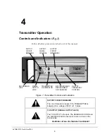
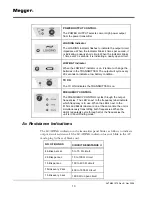
Figure 1: Transmitter Controls and Indicators.................................................................................... 9
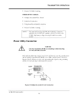
Figure 2: Multiple Grounded Circuit Connection ............................................................................. 13
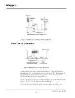
Figure 3: Multiple Ground Power Utility Application....................................................................... 14
Figure 4: Multiple Ground Telco Application................................................................................... 14
Figure 5: Flexible Coupler Connection............................................................................................. 15
Figure 6: Inductive Connection........................................................................................................ 16
Figure 7: Inductive Connection 30
°
Angle........................................................................................ 16
Figure 8: Direct Connection............................................................................................................. 17
Figure 9: Continuously Grounded Circuit......................................................................................... 18
Figure 10: Telephone Direct Shield Connection............................................................................... 19
Figure 11: Telephone Direct Pair Connection .................................................................................. 20
Figure 12: Receiver Controls and Indicators..................................................................................... 21
Figure 13: Locating the Cable or Pipe............................................................................................... 24
Figure 14: Determine Cable Path in Peak Mode............................................................................... 24
Figure 15: Depth Measurements 45° Angle Method......................................................................... 29
Figure 16: Signal Return through an Insulation Fault to Earth.......................................................... 31
Figure 17: Collapsible Ground Return Probe................................................................................... 32
Figure 18: Ground Return Probe Insertion....................................................................................... 33
Figure 19: Spoked Wheel Return Paths ............................................................................................ 33
Figure 20: Ground Return Probe Fault Locating.............................................................................. 34
Содержание L1070
Страница 2: ...L1070 and L1071 Portable Locator Instruction Manual...
Страница 4: ......
Страница 8: ...AVTM651070 Rev B Nov 2006 iv M...
Страница 16: ...M AVTM651070 Rev B Nov 2006 8 M...
Страница 44: ...M AVTM651070 Rev B Nov 2006 36 M...