


11. When testing completes, a small dialog appears in the middle of the screen showing the progress of the discharge
process (in volts). When the dialog disappears, the indicator will turn off.
12. Surge test automatically begins next. The leads that will be tested are identified by the green indicators to the left
of the LEAD buttons.
13. All other functions will be disabled and the test will run based on the parameters defined in the Test Configuration
currently assigned to the selected Asset. For example, if PD testing is disabled within the Test Configuration, none of
the PD elements will appear within the Surge test screen.
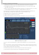
14. When voltage is applied to the test leads (automatically by the ADX), the LEADS ENERGIZED indicator in the top
right corner flashes until the leads have properly discharged; ADX front panel LEDs show which leads are energized.
The LEAD indicators in the screen turn off as each test completes.
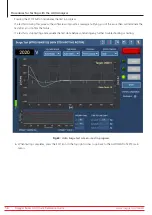
15. If the Surge tests pass, the sequence will automatically save the data and move onto the discharge screen or the
next programmed sequence step. Manual interaction and saving test data is only required if there is an interruption
in testing.
Before returning to the main menu, a message appears instructing you to allow the Asset sufficient time to discharge
before removing test leads. Depending on the Asset’s size and the amount of time high potential voltage has been
applied, this time will vary.
WARNING: To ensure the safety of all personnel, refer to “Ensure Proper Grounding
and Discharge after Conducting DC Tests” in chapter 1, “General Operating and Safety
Information” for guidance on properly discharging and grounding the Asset (DUT).
Fig 65:
Auto Surge test screen.
www.megger.com/baker
Megger Baker ADX Quick Reference Guide
62
Procedures for Testing with the ADX Analyzer


