Rear Panel Connections
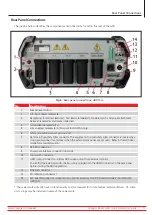
The graphic below identifies the components and connections found on the rear of the ADX.
Fig 6:
Rear panel connections; ADX15A.
No
Description
1
Breaker reset button.
2
A/C input power receptacle.
3
Receptacles for red test leads (3x). Test leads are labeled to facilitate match and proper attachment
between receptacles and device under test.
4
Ground lead receptacle (1x).
5
Armature test receptacle (in this space for ADX15A only).
6
Safety ground/power pack ground stud.
7
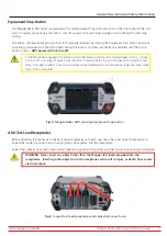
Remote E-Stop/safety lights connector. The equipment stop and safety lights connector is covered by a
stop Jumper connector and cover when the external accessories are not used. Refer to the ADX User
Guide for more information.
8
RS-485 connection.*
9
Power pack interface connector (optional).
10
Foot switch connector.
11
HDMI output connector—display ADX screen output to an external monitor.
Ensure that the external monitor being used is plugged into the HDMI connector on the back panel
before starting the ADX application.
12
Ethernet connector.
13
PD calibration connector.*
14
RLC adapter connector—Adapter is an optional accessory for ADX Standard models; included with
ADX15A.
* These elements currently have no functionality and are reserved for future feature implementation. On some
units, plugs may be installed in place of these elements.
www.megger.com/baker
Megger Baker ADX Quick Reference Guide
11
Rear Panel Connections


