background image

Table of Contents

1 — General Operating and Safety Information ............................................................. 1

Symbols and Labels used on Equipment   ....................................................................1
Icons and Terminology Used in this Guide ...................................................................2
Safety Precautions .........................................................................................................2

General ..........................................................................................................................2
Test Lead Safety Precautions ...........................................................................................3
Test Related Precautions .................................................................................................4

Ensure Proper Grounding and Discharge after Conducting DC Tests ...............................5

Installation Category Definitions .....................................................................................5

Safely Lifting the ADX  ..................................................................................................6
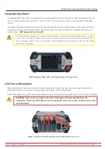
Equipment Stop Button ................................................................................................7
ADX Test Lead Receptacles ...........................................................................................7
General Operation, Maintenance, and Service Information ......................................8

Cleaning and Decontamination ......................................................................................8
Test Leads.......................................................................................................................8
Power Requirements ......................................................................................................8
Environmental Conditions ..............................................................................................8

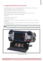
2 — Megger Baker ADX Instrument Overview   .............................................................. 9

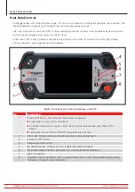
Front Panel Controls ......................................................................................................10
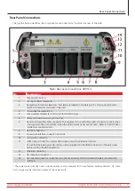
Rear Panel Connections ................................................................................................11
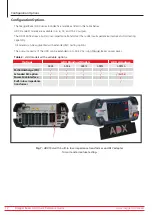
Configuration Options ..................................................................................................12
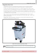
Megger Baker Power Packs ..........................................................................................13
Accessories .....................................................................................................................14

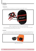
Carrying Case.................................................................................................................14
Footswitch .....................................................................................................................14
Remote E-Stop and Lights Accessory ..............................................................................15
Test Clips and Probes ......................................................................................................16
Armature Surge Test Fixture ............................................................................................17
Megger Test Probe and Accessories Options ...................................................................17

3 — ADX Software Overview ......................................................................................... 19

Focus is on the Asset .....................................................................................................19
Setting up Assets and Related Elements ......................................................................20
Test Configuration Editor .............................................................................................21

Top Section—General Information ..................................................................................22
RLC Tests Section............................................................................................................23
DC Tests Section .............................................................................................................24
Surge Tests Section .........................................................................................................25
Setting up Assets............................................................................................................26

www.megger.com/baker

Megger Baker ADX Quick Reference Guide

iii

Содержание Baker ADX

Страница 1: ...Megger Baker ADX Automated Diagnostic Test Equipment Quick Reference Guide...

Страница 2: ...www megger com Megger Baker ADX Quick Reference Guide...

Страница 3: ...eotaping facsimile and so on without written permission from Megger Baker Instruments Megger Baker Instruments assumes no liability for damages consequent to the use of this product Please read and th...

Страница 4: ...Megger Group Limited a manufacturer of electrical test equipment and measuring instruments for power applications acquired the Baker Instruments business from SKF Group in August of 2018 For over 50 y...

Страница 5: ...8 Test Leads 8 Power Requirements 8 Environmental Conditions 8 2 Megger Baker ADX Instrument Overview 9 Front Panel Controls 10 Rear Panel Connections 11 Configuration Options 12 Megger Baker Power Pa...

Страница 6: ...Sequence 38 Selecting an Asset to Test 39 Help Screens 40 Manual Tests 41 Manual Tests Main Screen 41 Manual RLC Test 42 Manual DC Tests 45 Manual Surge Test 49 Manual Coil Tests 51 Test Process Over...

Страница 7: ...ted on rear panel of instrument by the ground terminal Warning about hazardous voltage and risk of injury or death from severe electrical shock Located above the test leads on the back panel of the in...

Страница 8: ...r understanding of the risks from operating the instrument and adequate formal operating procedures and authorization to protect personnel from harm Do not exceed maximum operating capabilities of the...

Страница 9: ...en test leads with factory authorized parts to ensure safe operation and maintain performance specifications Use only Megger approved test leads with this instrument Ensure that hands remain behind fi...

Страница 10: ...rument is 1 0 F After capacitive loads are measured ensure that the test has terminated and that the load is safely discharged and protected from dielectric absorption if necessary before disconnectio...

Страница 11: ...to be removed before the full discharge time has elapsed secondary grounding equipment should be attached between the DUT and station ground before removing the test leads When a proper ground connec...

Страница 12: ...he unit Follow standard practice and safety procedures when lifting the unit Remove tripping hazards test leads power cord and all accessories before lifting The front cover should also be in place du...

Страница 13: ...ot stop an RLC test after it has been started Care must be taken when handling the unit and device under test even when the E Stop is activated Fig 2 Megger Baker ADX showing Equipment Stop button ADX...

Страница 14: ...with a cloth dampened with water Make sure the leads are dry before use Power Requirements Using the provided AC power cord connect the unit to a grounded AC power source The unit s power requirement...

Страница 15: ...andard ramp and step voltage Surge tests Low impedance armature and coil tests Armature and coil surge tests Megger Baker ADX testers are compatible with the Megger Baker PP and PPX series power packs...

Страница 16: ...X15 No Description 1 Power On Off button The button has three modes of operation Screen sleep Quick press and release Controlled shut down or restart Press one second and release then press Power Off...

Страница 17: ...ctor and cover when the external accessories are not used Refer to the ADX User Guide for more information 8 RS 485 connection 9 Power pack interface connector optional 10 Foot switch connector 11 HDM...

Страница 18: ...ded RLC testing options The output capacity of the ADX can be extended up to 40 kV by using Megger Baker power packs Table 2 ADX models with available options Options ADX Standard Models ADX Armature...

Страница 19: ...r PPX series is controlled by a precision regulated high voltage power supply output is not dependent on the incoming line voltage These units perform Surge and DC HiPot tests when used with the Megge...

Страница 20: ...a fully foam lined hard shell is also available The case has an extendable handle and wheels for easy transport Footswitch You can connect the footswitch optional to the Baker ADX host or auxiliary u...

Страница 21: ...remote E Stop is used to stop high voltage testing in the event of an emergency Fig 11 Remote E stop and lights accessory No Description 1 Remote Test Status Indication Lights E Stop TSIL ES 2 Remote...

Страница 22: ...obes ADX ASP used during armature bar to bar testing Fig 12 Megger ADX Armature Surge Hand held Probes The ADX Armature Surge Clips ADX ASC are commonly used during coil and DC motor testing The clips...

Страница 23: ...es Options A variety of test probe and accessory options are available for the ADX when the RLC adapter option is used The image below provides several examples of available accessories designed to se...

Страница 24: ...www megger com baker Megger Baker ADX Quick Reference Guide 18...

Страница 25: ...where saving data for long term use is not needed When testing without selecting an Asset ensure that the top line of the screen shows None Default indicating no Asset is selected If an Asset is selec...

Страница 26: ...ecifications you want to apply to the Asset Installation defines where the Asset is installed so operators know where to find the Asset Route defines a list of Assets and their Installations for sched...

Страница 27: ...creen to edit or copy existing Test Configurations or to create new ones New Test Configurations should be created before creating or editing Assets because you will assign available configurations du...

Страница 28: ...ectly to the Asset At Motor or to a remote testing junction At Switchgear Define other general attributes for the Test Configuration by pressing the ADD ATTRIBUTE button Fig 19 Test Configuration Edit...

Страница 29: ...fault value for the Correct To temperature field Temperature Compensation The analyzer will correct the coil resistance tests to the value entered in the Correct To field By default when creating a ne...

Страница 30: ...p down list helps you select the combination of IR DA PI Tests you want to execute The Temp Compensation drop down list is used to select the winding insulation type The selection adjusts the algorith...

Страница 31: ...nd more Line to line EAR TM limits can be applied to individual leads phases or to all leads Pulse to pulse EAR TM limits are applied to all leads Fig 23 Test Configuration Editor Surge Tests section...

Страница 32: ...d Installations In turn Installations and Assets are used to build Routes NOTE In many organizations such as repair or rewind shops Assets are not installed on machines Instead they are commonly assig...

Страница 33: ...ou have a motor that is similar to one shown in the list you can click on or touch the Asset to highlight it then touch the EDIT ASSET button to open it in the Asset Editor screen where it can be copi...

Страница 34: ...ibutes so only minor adjustments should be needed in those areas 5 Enter a new name in the Asset Name field following your organization s naming conventions 6 If the Asset Type and or Asset Sub type f...

Страница 35: ...ts in Automatic and Sequence modes Fig 28 Assigning Test Sequence and Test Configurations You can add Attributes to provide additional information about the Asset Attributes are used in the Asset Sele...

Страница 36: ...rts and manage assets installations and routes When an administrator adds new elements to the system or makes changes to existing elements updates are made to the connected ADX testers shortly after t...

Страница 37: ...ver can also be removed during use Remove the keyboard from the tray then remove the cover by holding it in a nearly closed position while simultaneously pressing up on the bottom corners just below t...

Страница 38: ...tand from the bottom of the unit 3 Press fingers into the kickstand bottom edge to release it Fig 31 Place ADX upright on back bumpers 4 Fully unfold the kickstand towards the front face of the unit t...

Страница 39: ...spective receptacles then lay out the cables as shown below before raising the unit vertically 2 Check to ensure that all leads are properly positioned and not being pinched in any manner 3 Ensure tha...

Страница 40: ...r respective receptacles on the back of the tester 3 Plug the ground cable into its receptacle on the back of the ADX 4 Label the leads on the Asset 1 2 and 3 5 Connect corresponding numbered test lea...

Страница 41: ...the ADX test leads are NOT coiled in any manner during testing to prevent interference with test results To avoid damaging the unit DO NOT coil excess test leads and place them on top of the ADX Ensur...

Страница 42: ...ave a functioning Wi Fi or Ethernet connection Before starting the ADX application touch and hold the top of the display screen and slowly drag your finger down the screen to pull down the Android sys...

Страница 43: ...cannot create or edit Assets and Test Configurations A Customer Admin user with full permissions is also provided A unique password assigned by Megger is required Contact Megger Baker Instruments Sup...

Страница 44: ...tive maintenance programs we suggest using a regimented testing sequence The approach involves conducting a series of progressively rigorous tests and if a test fails troubleshooting and repairing at...

Страница 45: ...practice selecting an Asset is the first step in all testing procedures Press the ASSETS icon in any main screen to open the Assets Selection screen 2 Use the tools available in Browse or Search Mode...

Страница 46: ...n of the related screen contents to help you understand how the screen is used Fig 40 Example Help screen For more detailed information on each screen and the overall ADX user interface refer to the M...

Страница 47: ...of this guide for complete safety information Manual Tests Main Screen Touching the MANUAL TESTS icon reveals a screen containing icons that provide access to manual RLC DC Surge and Coil tests Touch...

Страница 48: ...OTE Changes made here only affect the current testing session and will not be permanently saved to the selected test configuration From this screen you can make the following adjustments if needed Sel...

Страница 49: ...re restored before clicking OK 5 The RLC test registers the measurements taken on each test lead and compares them to the target values specified in the Test Configuration If the measured values are w...

Страница 50: ...DX User Guide for more information on interpreting the results displayed in this tab Fig 45 Manual Test RLC Y Delta tab NOTE RLC test results can be saved or overwritten with a retest while still in t...

Страница 51: ...Ramp Rate using the slider to provide a faster or slower ramp rate when applying test voltage Slower ramp rates can reduce issues with overshooting target voltages or incurring overcurrent conditions...

Страница 52: ...tify you of the issue before stopping the test 5 When a test fails you should troubleshoot and repair the Asset for the reported failure before continuing with your testing 6 When the IR DA PI tests c...

Страница 53: ...ng discharged When the message disappears the LEADS ENERGIZED light above the START STOP button will go out as will the front panel LEDs 9 Touch the Save icon in the bar at top right to save your resu...

Страница 54: ...e been tested Ensure that the time for each step is consistent The last step will be recorded as the final HiPot test 4 When you have completed all steps press the STOP button 5 A message will appear...

Страница 55: ...ations can use Auto Scale and the waveform will automatically adjust as you slowly increase the applied voltage By default the Surge Scale Y axis is set to Auto Scale As you ramp up the voltage the di...

Страница 56: ...able 11 Repeat the process for all leads that you want to test 12 When you have completed your testing touch the Save icon then the Exit icon to return to the main screen Fig 51 Manual Surge Test in p...

Страница 57: ...to bar readings from an armature commutator NOTE In this application an Asset typically refers to a type of coil rather than to a specific individual coil Assets can be created for a coil type and re...

Страница 58: ...53 Coil Test screen with example test in progress 4 When all coils have been tested for RLZ switch the ACTIVE TEST button to SURGE and set the coil to number 1 5 Press and hold the Push to Test butto...

Страница 59: ...r completed tests Press the LOGOUT icon to exit the interface when you have completed your tasks Fig 54 Automatic Tests main screen Before testing ensure that the test leads are properly connected to...

Страница 60: ...can enter the actual winding temperature value that will be used for temperature correction compensation Pressing the TEST ASSET button starts the test running Testing safety message screens appear ne...

Страница 61: ...motor frame and test lead three will be disconnected not contacting any motor lead or ground Fig 57 Auto RLC test change leads message for capacitance testing NOTE Acknowledge this message only after...

Страница 62: ...software adds markers to key points in the test process where IR DA and PI testing complete Markers also appear for HiPot tests If a test fails during this process the software will provide a message...

Страница 63: ...Configuration and all three test leads have been selected turned on for Surge testing 1 You can press START to continue testing as configured or you can select the Leads phases that you want to test...

Страница 64: ...firm the failure If a test fails stop testing and evaluate the test data before conducting any further troubleshooting or testing Fig 60 Auto Surge test screen test in progress 6 When testing complete...

Страница 65: ...ols to modify test sequences execute routes and run a fully automated programmed sequence of tests on a selected Asset Common controls help you select assets to test generate reports on test results a...

Страница 66: ...any user added connection and safety screens and then the screen for the first test type in the sequence Fig 62 Sequenced Tests mode Test Asset Test Initiation screen NOTE A sequence can include a nu...

Страница 67: ...edge this message only after the leads have been reconfigured After pressing the Continue Testing button the software will immediately continue with the next test in the sequence often DC Tests 10 Dur...

Страница 68: ...d ADX front panel LEDs show which leads are energized The LEAD indicators in the screen turn off as each test completes 15 If the Surge tests pass the sequence will automatically save the data and mov...

Страница 69: ...ter reviewing the results to return to the SEQUENCE TESTS main menu Fig 66 Auto Test Results Summary NOTE This example provides a simplified introduction to Sequence testing Refer to the Megger Baker...

Страница 70: ...at a time in the path The display area just below the path field lists the results of the search criteria specified The list can include test results or higher level virtual directories that contain t...

Страница 71: ...es or other information to enhance the report 4 If more than one test result was selected you can use the controls above the screen to page through each report 5 Press the Printer icon at the top righ...

Страница 72: ...ger USA Valley Forge Valley Forge Corporate Center 2621 Van Buren Avenue Norristown Pennsylvania 19403 USA T 1 610 676 8500 F 1 610 676 8610 Megger Limited Archcliffe Road Dover Kent CT17 9EN ENGLAND...

Отзывы: