1.
3 In-Use
OFF
Lines idled and unlocked
Steady ON
Lines in use and unlocked
Steady yellow
Shutting down
Yellow, blinking yellow, 1 cycle per second, 50% duty Locked
3 ETH1
Green, blinking, variable rate
Network traffic
Green, steady ON
No network traffic
OFF
Not connected
5 Power
Amber, steady ON
Restart completed
OFF
Indicates that the unit is not connected
Blinking, 1 Hz, 50% duty
Restart in progress
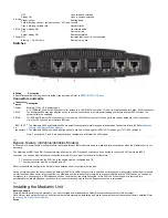
Switches
# Switch
Description
2 Reset/Default Allows setting the unit to default (known) values. Refer to
Connectors and cards
#
Connectors
/cards
Description
1 Power
External 12 Vdc 1.5 A power supply
3 ETH1
A 10/100 BaseT Ethernet RJ-45 connector for access to a LAN, WAN or computer. This port is by default used for uplink / WAN connection.
The Mediatrix 4400 may also offer the option to use this connector as a remote power feeding over Ethernet as per 802.3af when the
network offers the capability.
4 ETH2
10/100 BaseT Ethernet RJ-45 connector for access to a LAN, WAN or computer. These ports are used by default for LAN connections.
5
BRI 1 -BRI
4
connectors
Up to four RJ-45 connectors to attach BRI lines.
Feature (4402plus/4404plus Models)
The Mediatrix 4400plus models offer the option to use Power Feeding over ISDN in NT mode as per ITU-T I.430 (section 9).
Note: Connectors 2, 3, and 4 are optional and not available on all Mediatrix 4400 models.
Top
Bypass Feature (
)
4402plus/4404plus Models
In the event of a power failure or network failure, the optional bypass feature permits users to make and receive calls even when the Mediatrix unit is not
operating.
The Mediatrix unit BRI 1 and BRI 2 connectors may either act as a SCN bypass. For instance, if you decide to connect a SCN line into the BRI 2
connector, you can use a BRI telephone connected into the BRI 1 connector to make calls. Furthermore:
The connector on which the SCN line is connected must be configured as a TE.
The other connector must be configured as a NT.
Refer to the Software Configuration Guide for more details on how to configure the line type.
During normal operation, the direct connection between the BRI 1 and BRI 2 connectors is switched out through commuting relays and both ports resume
normal functions. When power is removed from the Mediatrix unit, the relay setting is restored to a connected state and the SCN line can be used as an
emergency line. Consequently, a BRI telephone used on the other port is directly connected to this SCN line. When the power is restored, this
automatically removes the Bypass connection; this means that any ongoing call on the Bypass connection is terminated.
Top
Installing the Mediatrix Unit
Before you begin
Warning: Before performing this procedure, you must first read and understand the Safety Recommendations listed in this document.
Note: Note or take a picture of your unit's serial number before starting the installation, and place the card stickers of the cards not factory installed. Refer
to
Locating the Product Serial Number
Steps


