background image


 USER`S MANUAL                                                                                              

ME-TUN


 File: ME-TUN Manual E.DOC                                

MEDIA ENGINEERING

                                      page 7/29   


A.2. INSTALLATION PROCEDURE 

 
Place the ME-TUN professional FM tuner in a horizontal position, and do not place anything 

heavy on it. Never bring a magnet or magnetized objects near the tuner, because such will 

adversely affect the performance of the ME-TUN. 


Should it be necessary to change the sampling rate of the digital audio output to another 

value than the factory set 48kHz please refer to chapter A3. 


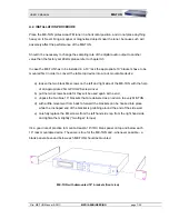
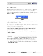
In case the ME-TUN has to be installed in a 19” rack the appropriate 19” brackets have to be 

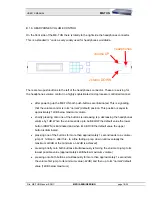
mounted first in order to convert the table top device into a rack mountable device: 


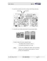
a)  loosen the two black M4 screws on the left and right side of the ME-TUN with the help 

of an appropriate 2.5mm PHILIPS screw driver 

b)  put the two screws beside for they will be used again at the end 

c)  unpack the two blue 19” brackets that are delivered as an add-on to every ME-TUN 

d)  with a little movement from back to forward the brackets can be hooked into place 

while the U-shaped end of the bracket is grabbing around the end of the side wall. 

e)  carefully replace the M4 screws from the left hand side rsp. from the right hand side 

and tighten them slightly (“two finger” torque) 


It’s a good rule of practice to mount at least a 19”/1RU blank panel on top and below each 

19” rack mountable device. The same is true for the ME-TUN and - whenever possible - a 

blank panel above and below each ME-TUN should be mounted. 


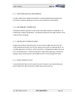
ME-TUN with demounted 19” brackets (front view) 

Содержание ME-TUN

Страница 1: ...ing com web www mediaengineering com www me tun com www fm spy com MEDIA ENGINEERING Markus Stocker Professional Broadcasting Systems Rainstr 15 CH 8104 WEININGEN ZH Switzerland Phone 41 1 750 66 88 F...

Страница 2: ...akes no representations or warranties whatsoever with respect to the content of this document and specifically disclaims any implied warranties of merchantability or fitness for any particular purpose...

Страница 3: ...consisting of one 19 1RU rack mountable device in its original metal housing conforms to the following standards Standards used EN 55022 1998 A1 2000 EN 55024 1998 A1 2001 FCC PART 15 Test center EMC...

Страница 4: ...ATIONS 12 B 1 1 STARTUP SEQUENCE 12 B 1 2 LIT UP KEYS 12 B 1 3 THE INITIAL STATE 13 B 1 4 TUNING IN TO A SPECIFIC FREQUENCY 14 B 1 5 SAVING A PRESET 15 B 1 6 LOADING A PRESET 16 B 1 7 SETTING THE INFO...

Страница 5: ...harged with the help of a suitable resistor When the equipment is open components that carry havy electrical loads such as power transistors and resistors as well as solenoid coils should not be touch...

Страница 6: ...he contrast of the LCD display A 1 3 CAUTION WITH THE MAINS CABLE Always seize the mains cable at the plug Do not pull on the cable and never touch the mains cable with wet hands since this can cause...

Страница 7: ...loosen the two black M4 screws on the left and right side of the ME TUN with the help of an appropriate 2 5mm PHILIPS screw driver b put the two screws beside for they will be used again at the end c...

Страница 8: ...Y CONDITIONS in chapter A 1 on page 5 2 disconnect all cables from the ME TUN Make shure there is no power line connected anymore and the power switch is off 3 loosen the three black M3 screws on the...

Страница 9: ...te and select the propre jumper setting fs J1 J0 96 kHz 0 0 48kHz 0 1 44 1 kHz 1 0 32kHz 1 1 J1 J0 The table indicates the jumper settings as follows 0 indicates that no jumper has to be set 1 indicat...

Страница 10: ...rection in order to allow the bended shielding at the back grabing the U shaped rear side 17 put in place the three black M3 screws in order to hold down the cover Make shure the propre screws are use...

Страница 11: ...r cord This decoupling prevents that the potential of the antenna cable which is very seldom earth is short circuited with the earth supplied by the power supply for this were leading to compensation...

Страница 12: ...r to section B 1 3 INITIAL STATE on page 13 B 1 2 LIT UP KEYS ME TUN has quite a large number of keys but is nevertheless operated very simply Only the lit up keys react on user input No matter in wha...

Страница 13: ...plus the letters A or B in order to indicate the actual antenna input in use The lower half of the LCD display is showing one out of three possible information lines described in B 1 7 SETTING THE IN...

Страница 14: ...digit of the desired frequency In case of inputting 103 250MHz this would be a 1 and the screen and keypad looks like this screen 3 1 2 3 LOAD DISP 4 PGM 5 25kc 6 LOCK 0 SCAN 7 PGM 8 25kc 9 ANTA B SA...

Страница 15: ...25kc 9 ANTA B SAVE MENU keypad 3 INITIAL STATE whereupon screen 4 will appear on the LCD display and the ME TUN will ask for a preset number in order to know where to save the preset Preset numbers b...

Страница 16: ...eypad 4 points to the LOAD key plus a 2 digit preset number to load between 00 and 39 has to be keyed in 1 2 3 LOAD DISP 4 PGM 5 25kc 6 LOCK 0 SCAN 7 PGM 8 25kc 9 ANTA B SAVE MENU keypad 4 INITIAL STA...

Страница 17: ...n in dB V the reference level is 1 V what equals 0dB V e g 46dB V 200 V 3 RDS data of the PSNS code program service name segment If the actually tuned in station is not broadcasting any RDS informatio...

Страница 18: ...ume shortly pressing onto one of the buttons is increasing rsp decreasing the headphones volume by 1dB When the volume ends up to be BELOW the default value the lower button DOWN is illuminated and wh...

Страница 19: ...SCAN 7 PGM 8 25kc 9 ANTA B SAVE MENU keypad 6 INITIAL STATE A double press of the SAVE MENU button is switching to the MENU functions and the LCD display of the ME TUN will look like screen 6 screen 6...

Страница 20: ...and PGM keys for in crementing rsp de crementing the preset number out of the MENU state refer to section B 2 1 MENU FUNCTIONS on page 19 1 2 3 LOAD DISP 4 PGM 5 25kc 6 LOCK 0 SCAN 7 PGM 8 25kc 9 ANTA...

Страница 21: ...he FM receivers tuning frequency in 25kHz steps up or down 1 2 3 LOAD DISP 4 PGM 5 25kc 6 LOCK 0 SCAN 7 PGM 8 25kc 9 ANTA B SAVE MENU keypad 10 MENU When pressing one of these buttons continuously the...

Страница 22: ...B SAVE MENU keypad 11 The entire sequence to lock the ME TUN is MENU MENU LOCK As soon as the LOCK button is activated the following screen and keypad lightmap will appear screen 7 1 2 3 LOAD DISP 4 P...

Страница 23: ...first channel ME TUN finds will be saved to program number 39 the second one to program number 38 and so on As the user of ME TUN will normally have his favourite channels stored in the first few pre...

Страница 24: ...d is set to 50dB V the center key 5 on the keypad will light up briefly and the preset number on the LCD display will be decremented by 1 After reaching the bottom end of the FM band 87 500MHz ME TUN...

Страница 25: ...g on the previous selection of the antenna input Note ME TUN is featuring two antenna inputs for there are situations in which it s necessary to monitor not only radio stations that can be received wi...

Страница 26: ...0067 6 Opto1 Emitter RDS loss alarm 7 Opto2 Emitter STEREO loss alarm 8 Opto3 Emitter CARRIER loss alarm 9 Opto4 Emitter TA flag 10 Opto5 Emitter TP flag 11 for future use 12 for future use 13 Gnd Cha...

Страница 27: ...c diagram represents the internal ciruitry of the ME TUN in regard of the AUXILIARY INTERFACE Also two application examples are shown the implementation of relais coupled switching outputs with the us...

Страница 28: ...9 LOAD 1 9 SEQUENCING THE INFO MODE DISP DISP STEPPING UP THROUGH PRESETS MENU MENU PGM PGM STEPPING DOWN TROUGH PRESETS MENU MENU PGM PGM FINE TUNING IN 25kHz STEPS UPWARDS MENU MENU 25kc 25kc FINE T...

Страница 29: ...oss threshold RF signal strength 25dB V number of presets 40 ALARM OUTPUTS connector type D Sub 25 pin female chassis receptacle alarm outputs 5 photocouplers specification photocouplers UCEmax 40V IC...

Отзывы: