3
PMG3 instruction manual - July 2011 rev. 01
5
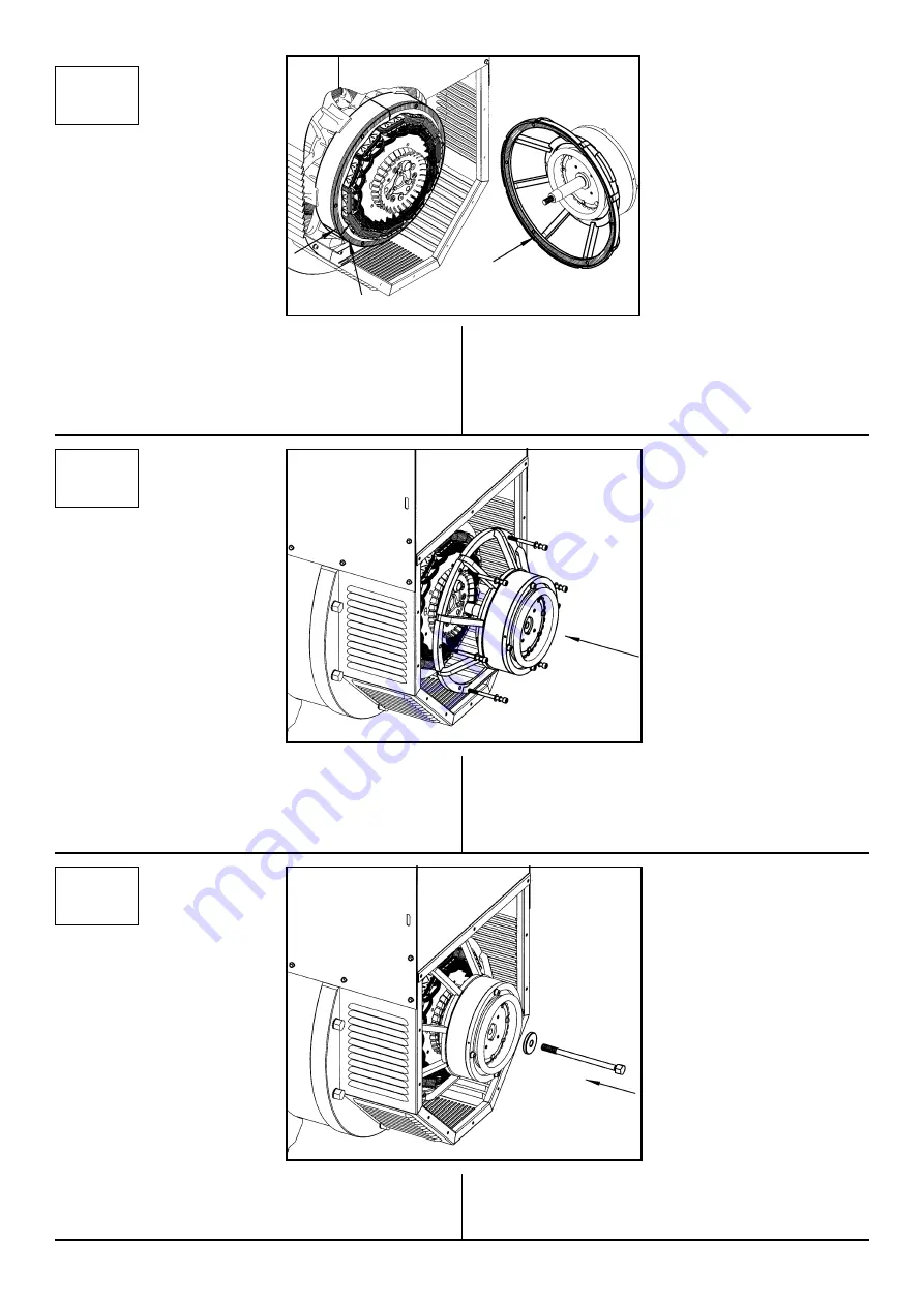
5) Accostare il “PMG ma” allo statore eccitatrice,
con i cavi rivolti verso l’alto, centrare la flangia dello
statore eccitatrice e l’albero nelle relative sedi. Avvi-
tare le 6 viti M8 in dotazione applicando una coppia
di 21 Nm.
5) Move next the "PMG ma" the exciter stator, with
the wires facing up, center the flange of the stator
exciter shaft in their seats. Tight the 6 screws M8
supplied by applying a torque of 21 Nm.
6
6) Avvitare il tirante centrale M14, dotato della rela-
tiva rondella, applicando una coppia di 120 Nm.
6) Tighten the central stud M14, equipped with wa-
sher, with a torque of 120 Nm.
4
4) Pulire il bordo della superficie dello statore eccita-
trice (a), sede della flangia di accoppiamento “PMG
ma” (b), dalla vernice protettiva.
Rimuovere il pelabile di protezione dalla superficie
interna della flangia “PMG ma” (b).
4) Clean the edge of the exciter stator (a), seat of the
flange coupling "PMG ma” (b), by taking off the pro-
tective coating.
Remove the peel-off protection from the inside sur-
face of the flange "PMG ma” (b).
(a)
(b)
(a)


