background image

“SE

 Series

” Service and Parts Manual

March

 201

7

Page 1-3

P

R E

-S

T A R T

 I

N S P E C T I O N

 C

H E C K L I S T

P

RE

-S

TART

 I

NSPECTION

 C

HECKLIST

Items on this checklist should be inspected before each work shift.  

A copy of this checklist is available in the notes section of this manual.

Photocopy the Pre-Start Inspection Checklist to keep record of this inspection.

30-D

AY

 S

ER VICE

The 30 day maintenance procedure is a one-time procedure to be performed after the 
first 30 days or 40 hours of usage. These procedures are also performed at later 
intervals.
Maintaining the tires and wheels in good condition is essential to safe operation and 
good performance. Tire and/or wheel failure could result in a machine tip-over. 
Component damage may also result if problems are not discovered and repaired 
quickly.

1. Check the tire surface and sidewalls for cuts, cracks and unusual wear.
2. Check each wheel for damage, bends and cracks.
3. Check each wheel bolt for proper torque (38 ft-lbs/51 Nm dry).

H

YDRAULIC

 F

ILTER

 & B

REATHER

 C

AP

Replace the Hydraulic Filter element 
after the first 30 days of machine use.
After that, replace the Breather Cap 
Filter and Hydraulic Filter every 6 
months or 300 hours (whichever 
comes first).
If the machine is used in very dusty, 
exceptionally hot or exceptionally cold 
conditions, replace the Breather Cap 
Filter and Hydraulic Filter every 3 
months or 150 hours (whichever 
comes first).

F

REQUENT

 I

NSPECTION

 C

HECKLIST

THIS CHECKLIST MUST BE USED AT 3-MONTH INTERVALS OR EVERY 
150 HOURS OF MACHINE USE, WHICHEVER OCCURS FIRST. FAILURE TO 
DO SO COULD RESULT IN DEATH OR SERIOUS INJURY.

Frequent Maintenance Inspections should be conducted by qualified service 
technicians only. Photocopy the Frequent Inspection Checklist page from the 
Operator’s Manual to keep record of this inspection. Keep inspections records up to 
date. Record and report all discrepancies to your supervisor. 
Perform all checks listed on Pre-Start Inspection, then proceed with the following 
checks.

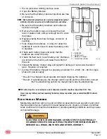
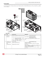
ART_5124

Hydraulic
Reservoir

Hydraulic
Filter

Controls
Tray

Breather Cap

Содержание 1930SE

Страница 1: ...SERVICE AND PARTS MANUAL ART_4908 SE Series Serial Number Range 16800001 Up Part 94124 March 2017 1930 2632 3346 4046 4555 ...

Страница 2: ...CA 93630 USA Ph 1 800 387 4575 1 559 842 1500 FAX 1 559 842 1520 E mail info MECawp com Web www MECawp com Aerial Platform Sales Corp Revision History Original Release Date March 2017 Date Reason for Update March 2017 New Release ...

Страница 3: ... 1 2 Pre Start Inspection Checklist 1 3 30 Day Service 1 3 Hydraulic Filter Breather Cap 1 3 Frequent Inspection Checklist 1 3 Steering Yokes 1 4 Hydraulic Fluid 1 4 Batteries 1 4 Electrical Wiring 1 5 Tires Wheels 1 6 Emergency Stop 1 6 Key Switch 1 7 Horn 1 7 Drive Brakes 1 7 Drive Speed Stowed 1 8 Drive Speed Raised 1 8 Drive Speed Slow 1 9 Hydraulic Oil Analysis 1 9 Tank Venting System 1 9 Mod...

Страница 4: ...2632SE 3346SE 4046SE 4555SE 3 4 2632SE 3346SE 4046SE 4555SE 3 5 Hydraulic Schematic Hydraulic Control Unit HydraulicSchematic Hydraulic Control Unit Function Valve Electrical Schematic 1930SE 3 7 1930SE 3 8 4555SE 3 9 Harness Control Circuit 2632SE 3346SE 4046SE 4555SE 3 10 Wiring Diagram 1930SE 2632SE 3346SE 4046SE 4555SE 3 11 1930SE 2632SE 3346SE 4046SE 4555SE 3 6 Harness Control Circuit Electri...

Страница 5: ... MEC parts to ensure proper operation and reliable perfor mance To obtain maximum benefits from your MEC Aerial Work Platform always follow the proper oper ating and maintenance procedures Only trained authorized personnel should be allowed to oper ate or service this machine Service personnel should read and study the Operator s Service and Parts Manuals in order to gain a thorough understanding ...

Страница 6: ...ance Stowed 3 25 in 8 3 cm 4 in 10 cm 4 in 10 cm Ground Clearance Elevated 625 in 1 6 cm 7 in 2 cm 7 in 2 cm Drive Speed Proportional Stowed 0 2 8 mph 0 4 5 km h 0 2 5 mph 0 4 km h 0 2 5 mph 0 4 km h Raised or extended 0 5 mph 0 8 km h 0 5 mph 0 8 km h 0 5 mph 0 8 km h Gradability 25 14 25 14 25 14 Maximum Side Slope Stowed 5 5 5 Tilt Sensor Settings 2 side to side 3 fore and aft 2 side to side 3 ...

Страница 7: ...m 7 in 2 cm Drive Speed Proportional Stowed 0 2 5 mph 0 4 km h 0 2 5 mph 0 4 km h Raised or extended 0 5 mph 0 8 km h 0 5 mph 0 8 km h Gradability 25 14 25 14 Maximum Side Slope Stowed 5 5 Tilt Sensor Settings 2 side to side 3 fore and aft 2 side to side 3 fore and aft Ground Pressure Wheel 167 psi 11 7 kg cm2 256 psi 18 kg cm2 Maximum Wheel Load 2948 lb 1340 kg 3076 lb 1395 kg Occupied Floor Pres...

Страница 8: ...nd procedures demonstrate our commitment to Quality and our relent less ongoing efforts towards Continuous Improvement due to which product specifica tions are subject to change without notice Any procedures not found within this manual must be evaluated by the individual to assure oneself that they are proper and safe Your MEC Aerial Work Platform has been designed built and tested to provide man...

Страница 9: ...onomical oper ation of your aerial work platform It will help to assure that your equipment will perform satisfactorily with a minimum of service and repair The actual operating environment of the machine governs the inspection schedule Cor rect lubrication is an essential part of the preventative maintenance to minimize wear on working parts and ensure against premature failure By maintaining cor...

Страница 10: ...ear of the scissor stack On the 2632SE and 3346SE the Maintenance Lock is located at the front of the scissor stack 1 Raise the platform approximately just high enough to rotate the Maintenance Lock into place 2 Lift the Maintenance Lock move it to the center of the scissor arm then rotate it up to a vertical position The Maintenance Lock must engage the scissor section above it DO NOT set it so t...

Страница 11: ... THE MAINTENANCE LOCKS 4046SE AND 4555SE Machines 1 Raise the platform approximately 13 ft 4 m from the ground just high enough to rotate 2 3 Lift the ladder end Maintenance Lock move it to the center of the scissor arm then rotate it down to a vertical position Use the machine entry ladder to reach the rear Maintenance Lock The Front End Maintenance Lock must engage the scissor section above it D...

Страница 12: ...lide the ladder end Maintenance Lock to the side and rotate it stowed position Use the machine entry ladder to reach the rear Maintenance Lock 3 Slide the front end Maintenance Lock to the side and rotate it stowed position 4 Lower the platform Keep clear of the scissor linkage when lowering If a Maintenance Lock requires adjustment to stow it correctly stop the lowering function Adjust the mainte...

Страница 13: ...positive battery cable first When the negative cable is installed a spark will occur if contact is made between the positive side of the battery and a metal surface on the machine This can cause damage to the electrical system battery explosion and personal injury TOTAL SYSTEM FAILURE TO PERFORM PREVENTIVE MAINTENANCE AT RECOMMENDED INTERVALS MAY RESULT IN THE UNIT BEING OPERATED WITH A DEFECT THA...

Страница 14: ...n Release Lift Cylinders Chassis Tie Down Lift Points Entry Gate Main Platform Lower Controls Emergency Lowering Handle Batteries Motor Controller Hydraulic Pump Motor Hydraulic Tank Entry Ladder Forklift Pocket Pothole Guard Forklift Pocket Battery Tray Controls Tray Maintenance Lock Maintenance Lock Guard Rails Manuals Case Deck Extension Battery Charger Battery Charger Main Power Switch ...

Страница 15: ... X 3 00 M3 X 3 00 6 16 29 52 85 130 172 247 332 423 637 872 8 20 35 62 103 158 210 301 404 517 779 1066 8 21 5 39 70 115 176 233 335 450 573 863 1181 11 27 47 84 139 214 284 408 547 700 1055 1444 9 23 42 75 120 176 240 343 472 599 898 1224 11 27 52 91 146 216 294 426 576 732 1098 1496 12 31 57 102 163 238 325 465 639 812 1217 1658 15 36 5 70 123 198 293 398 577 780 992 1488 2027 Torque values appl...

Страница 16: ... Components Torque Table parts drawings and service instructions in this manual packaging and instruction sheets provided with new parts instruction manuals provided by the manufacturer of the component being serviced Type SAE PORT SERIES Cartridge Poppet Fittings Hoses Ft Lbs Nm Ft Lbs Nm In Lbs Nm 4 N A N A N A N A 135 145 15 16 6 N A N A 10 20 14 27 215 245 24 28 8 25 30 31 41 25 30 34 41 430 4...

Страница 17: ...h an EMERGENCY STOP switch at the base controls and the platform control box Press the EMERGENCY STOP switch at any time to stop all machine functions Turn switch clockwise to reset Either switch will stop all machine functions Both switches must be reset or machine will not operate EMERGENCY LOWERING Figure 1 3 Emergency Lowering The Emergency Lowering System is used to lower the platform in case...

Страница 18: ... brakes have been released Resetting Brakes Press the Emergency Stop button then push the Brake Release Switch to the right to reset the brake 2632SE 3346SE 4046SE 4555SE 1 Chock the wheels 2 Turn the Key Switch to the OFF position 3 Pull or turn the red Emergency Stop button clockwise to the on position at both the ground and platform controls 4 At the Ground Controls panel press and hold the Lif...

Страница 19: ...e platform and reset the Platform Emergency Stop Switch Test platform control functions Select slow drive speed mode Carefully drive the machine off the transport vehicle with the winch attached Note The brakes are automatically released for driving and will automatically apply when the machine stops Winching Disengage brakes see Free wheel configuration for Winching or Towing on page 42 Carefully...

Страница 20: ...for loose or unsecured items Chock the wheels Use the tie down points on the chassis for anchoring down to the transport surface Use chains or straps of ample load capacity Use a minimum of four 4 chains or straps Adjust the rigging to prevent damage to the chains and the machine ART_5031 SE Series Service and Parts Manual March 2017 ...

Страница 21: ...nt trays are closed and secure Remove all loose items from the machine Determine the center of gravity of the machine Attach rigging to the designated lift points only Adjust the rigging to prevent damage to the machine and to keep the machine level Model X Axis Y Axis 1930SE 25 5 in 4 8 cm 23 3 in 59 1 cm 2632SE 31 7 in 80 6 cm 22 7 in 57 6 cm 3346SE 32 7 in 83 cm 26 9 in 68 2 cm 4046SE 32 7 in 8...

Страница 22: ... of supporting the weight of the machine Refer to Machine Specifications on page II for machine weights for your model of scissor lift 2 Chock tires on one end of machine and raise the other end of machine 3 Position a jack at the end of the machine to be lifted under a solid lifting point in the center of the frame 4 Raise the machine and place two 2 suitable jack stands under solid support point...

Страница 23: ... SE Series Service and Parts Manual March 2017 NOTES ...

Страница 24: ...ries 1 4 Electrical Wiring 1 5 Tires Wheels 1 6 Emergency Stop 1 6 Key Switch 1 7 Horn 1 7 Drive Brakes 1 7 Drive Speed Stowed 1 8 Drive Speed Raised 1 8 Drive Speed Slow 1 9 Hydraulic Oil Analysis 1 9 Tank Venting System 1 9 Module Latch Components 1 10 Limit Switches 1 10 Up Limit Switch 1 12 Level Sensor 1 12 Pothole Limit Switches 1 12 Annual Inspection Checklist 1 13 Scissor Slide Blocks 1 13...

Страница 25: ...E SCISSOR ASSEMBLY WITH THE MAINTENANCE LOCK SEE THE INTRODUCTION PORTION OF THIS MANUAL PERFORM SCHEDULED MAINTENANCE AT RECOMMENDED INTERVALS FAILURE TO PERFORM SCHEDULED MAINTENANCE AT RECOMMENDED INTERVALS MAY RESULT IN A DEFECTIVE OR MALFUNCTIONING MACHINE AND MAY RESULT IN INJURY OR DEATH OF THE OPERATOR KEEP MAINTENANCE RECORDS CURRENT AND ACCURATE IMMEDIATELY REPORT ANY DAMAGE DEFECT UNAUT...

Страница 26: ... wheel bolt for proper torque 38 ft lbs 51 Nm dry HYDRAULIC FILTER BREATHER CAP Replace the Hydraulic Filter element after the first 30 days of machine use After that replace the Breather Cap Filter and Hydraulic Filter every 6 months or 300 hours whichever comes first If the machine is used in very dusty exceptionally hot or exceptionally cold conditions replace the Breather Cap Filter and Hydrau...

Страница 27: ...ecification Chevron Ultra duty grease EP NLGI 1 lithium based or equivalent HYDRAULIC FLUID Inspect the condition of hydraulic fluid in the reservoir Oil should be a clear and amber in color BATTERIES Proper battery condition is essential to good machine performance and operational safety Improper or damaged cables and connections can result in component damage and hazardous conditions ELECTROCUTI...

Страница 28: ...UITS COULD RESULT IN DEATH OR SERIOUS INJURY REMOVE ALL RINGS WATCHES AND OTHER JEWELRY ART_5120 a Batteries b 300A Fuse c Battery Charger d Quick Disconnect 4 Be sure that the battery retainers and cable con nections are tight 5 Remove the battery caps and inspect the fluid level If plates show add just enough fluid to cover the plates 6 Replace cables that show damage corrosion or swelling 7 Ful...

Страница 29: ... the ECU and platform controls All wire harness connectors Level sensor 7 Raise the platform and return the Maintenance Locks to the stowed position see the Introduction portion of this manual 8 Lower the platform to the stowed position and turn the machine off TIRES WHEELS Maintaining the tires and wheels in good condition is essential to safe operation and good performance Tire and or wheel fail...

Страница 30: ...using the platform controls Do not stand in the platform 1 Turn the red Emergency Stop button clockwise to the on position at both the ground and platform controls 2 Turn the key switch to platform control 3 Check the up down function from the ground controls Result The machine functions should not operate 4 Turn the key switch to ground control 5 Check the machine functions from the platform cont...

Страница 31: ...e of hesitation jerking and unusual noise over the entire proportionally controlled speed range Perform this procedure with the machine on a firm level surface that is free of obstructions 1 Create start and finish lines by marking two lines on the ground 40 ft 12 2 m apart 2 Turn the key switch to platform control and turn the red Emergency Stop button clock wise to the on position at both the gr...

Страница 32: ...ance and service life Dirty oil may cause the machine to perform poorly and continued use may cause component damage Extremely dirty conditions may require oil changes to be performed more often Before replacing the hydraulic oil the oil may be tested by an oil distributor for specific levels of contamination to verify that changing the oil is necessary Hydraulic oil should be tested yearly and re...

Страница 33: ...e machine on a firm level surface that is free of obstructions DOWN LIMIT SWITCH The Down Limit Switch alerts the system when the platform is elevated above 6 5 feet 2 m 1 Remove the platform controls from the platform 2 Set the Maintenance Locks see the Introduction portion of this manual DEATH OR SERIOUS INJURY HAZARD NEVER PERFORM WORK OR INSPECTION ON THE MACHINE WITH THE PLATFORM ELEVATED WIT...

Страница 34: ...isplay will show code 18 and an alarm sounds The machine is func tioning properly Result The diagnostic display does not show code 18 and the alarm does not sound Replace the Down Limit Switch 14 Raise the platform until the pothole guards are deployed Result The diagnostic display does not show code 18 and the alarm does not sound The machine is functioning properly Result The diagnostic display ...

Страница 35: ...ly 6 6 ft 2 m Result The alarm sounds and the machine stops lifting after the pothole guards are deployed The machine is functioning properly Result The alarm does not sound and the machine will continue to lift the platform after the pothole guards are deployed Adjust or replace the Level Sensor 3 Press the drive function select button Standing on the up hill side of the machine attempt to steer ...

Страница 36: ...ATH OR SERIOUS INJURY Annual Maintenance Inspections should be conducted by qualified service technicians only Photocopy the Annual Inspection Checklist page from the Operator s Manual to keep record of this inspection Keep inspections records up to date Record and report all discrepancies to your supervisor Perform all checks listed on Pre Start Inspection and the Frequent Inspection then check a...

Страница 37: ...machine performance and service life Dirty oil may cause the machine to perform poorly and continued use may cause component damage Extremely dirty conditions may require oil changes to be performed more often Before replacing the hydraulic oil the oil may be tested by an oil distributor for specific levels of contamination to verify that changing the oil is necessary Hydraulic oil should be teste...

Страница 38: ...n the stowed position Fill as needed 2 Hydraulic Cap Breather Filter And Hydraulic Filter Breather Filter located inside Filler Cap Hydraulic Filter Canister Scheduled Maintenance Normal Conditions Change every six months or 300 hours whichever occurs first Severe Conditions very dusty exceptionally hot or exceptionally cold conditions Change every three months or 150 hours whichever occurs first ...

Страница 39: ...March 2017 Page 1 16 SE Series Parts Section NOTES ...

Страница 40: ... SE Series Service and Parts Manual March 2017 Page 2 1 Section 2 CONTROL SYSTEM CONTENTS PAGE Control Component Locations 2 2 Fault Codes 2 3 Parameter Adjustment 2 11 ...

Страница 41: ...OCATIONS CONTROL COMPONENT LOCATIONS ART_5125 Platform Controls PCU Lift Cylinders Lower Controls Batteries Motor Controller ECU2 Hydraulic Pump Motor Hydraulic Tank Functions Manifold Hour Meter ECU Battery Tray Controls Tray Battery Charger Battery Charger Main Power Switch ...

Страница 42: ...ure Sensor Fault All Models ECU Check the ECU System Communication Fault All Models 1 Check the platform Control 2 Check the wiring on platform control connector 3 Check the ECU 4 Check the battery 5 Check the relay on ground control All Models All Models SOLUTIONS Reset the option code 1 Check the wiring on toggle switch 2 Check the toggle switch All Models 1 Check the pothole board and switches ...

Страница 43: ...orm Joystick not in neutral at power up Message Not Used All Models Check the forward solenoid and wiring Check the option code 53 Drive reverse coil fault Not Used All Models Check the backward solenoid and wiring Check the option code 54 Lift Up Coil Fault All Models Check the lift solenoid and wiring 55 Lift Down Coil Fault All Models Check the down solenoid and wiring 56 Right Turn Coil Fault ...

Страница 44: ...l needed try replacing the Motor Controller 63 Motor Controller Motor Output Fault All Models 1 Check the drive motor and wiring 2 Check the drive motor controller Remark To make sure the drive motor is good before change the drive motor controller or the motor controller will be and wiring damaged again enable delay with the MEC Scissor Programmer it may be too short Make sure other Motor Control...

Страница 45: ...rrent in the motors when there should not be This could occur anytime the MC thinks the brakes are on and the motors are still turning This message sometimes comes just before other faults but should be ignored in those cases Or the steering voltage from the ECU was at some point outside of the range that was recorded during the training session Retrain the ZAPI and or check for fluctuating voltag...

Страница 46: ...e Motor Controller 77 Motor Controller Right Drive Motor Fault All Models Motor Controller Right Drive Motor Fault Check connections to the motors Cycle power to the lift and if that does not resolve the issue replace the Motor Controller 78 Pump Motor Short Fault All Models Pump Motor Short Fault Check connections to the pump motor Cycle power to the lift and if that does not resolve the issue re...

Страница 47: ...ntroller or the drive motor will be damaged again 2 Check the wires to right drive motor 3 Check the ZAPI controller and wiring 83 Left Brake Coil Fault 1930SE Only All Models 1 Check the left motor brake and wiring 2 Check the brake module and wiring 1 Check the wiring on left drive motor and brake Remark To make sure the drive motor is good before change the ZAPI motor controller or the drive mo...

Страница 48: ...ssociated NO FAULT MODELS 1 No drive no alarm the rest functions all good 1 Check the option code 2 Check the drive speed setting 3 Check the drive motor and wiring 4 Check the drive motor controller and wiring SOLUTIONS All Models 2 No steering no alarm the rest functions all good 1 Check the steering function valve 2 Check the steering overflow valve 3 Check the steering speed setting 4 Check th...

Страница 49: ... the emergency lowering cable All Models 9 Will not lift rated capacity 1 Check the lift relief valve by turning the adjuster screw clockwise 1 4 turn 2 Check the seal on lift relief valve 3 Check the seal on lift function valve 4 Check the pump All Models 10 No power on machine 1 Check the platform control and wiring 2 Check the charger relay wiring 3 Check three power switches and wiring 4 Check...

Страница 50: ...O MAKING THE CHANGE The following adjustments are made at the Platform Controls station using the LED Indicator to display the current settings Follow the instructions to reach the desired setting Change the setting by using the Steer Buttons on top of the control handle The right button increases the setting The left button decreases the setting Number represent a percentage 99 means 99 9 9 dot b...

Страница 51: ...he HORN and LIFT buttons then twist the Platform Emergency Stop Switch to the ON position 4 PS and the current Lift Speed setting will alternate on the LED Indicator Refer to the following pages for individual operating adjustments SAVING NEW VALUES New values must be saved immediately after adjustment To save new values press and hold the Horn button for 3 seconds To operate the machine with new ...

Страница 52: ... see Saving New Values on page 2 8 LOW SPEED DRIVE This parameter controls low speed drive when the platform is in the stowed position and Low Speed is selected turtle icon 1 Press the Drive Mode Select button The button will light up indicating this mode is active 2 Press and hold the Low Speed Mode Select button turtle icon The button will light up and the LED Indicator will show the present set...

Страница 53: ... on top of the Control Handle 4 Elevated Drive Speed can be set from 00 to 9 9 but must not be set higher than 50 Factory setting is 50 DO NOT ADJUST THE SETTING HIGHER THAN 50 5 Save the new setting see Saving New Values on page 2 8 LIFT SPEED This parameter controls the speed at which the platform elevates 1 Press the Lift Mode Select button The button will light up indicating this mode is activ...

Страница 54: ...de Select button The button will light up indicating this mode is active 2 Press and hold the Horn button and the Low Speed Mode Select button turtle icon 3 Adjust the speed using the steer left and steer right buttons on top of the Control Handle 4 Steering Speed can be set from 00 to 9 9 Factory setting is 30 5 Save the new setting see Saving New Values on page 2 8 ART_5134 ...

Страница 55: ... SE Series Service and Parts Manual March 2017 Page 2 16 NOTES ...

Страница 56: ...c 2632SE 3346SE 4046SE 4555SE 3 4 Hydraulic Control Unit 2632SE 3346SE 4046SE 4555SE 3 5 Electrical Schematic Harness Control Circuit 1930SE 3 8 4555SE 3 9 Harness Control Circuit 2632SE 3346SE 4046SE 4555SE 3 10 Wiring Diagram 1930SE 2632SE 3346SE 4046SE 4555SE 3 11 Function Valve 1930SE 2632SE 3346SE 4046SE 4555SE 3 6 Electrical Schematic 2632SE 3346SE 4046SE 1930SE 3 7 ...

Страница 57: ... and Parts Manual March 2017 Page 3 2 HYDRAULIC SCHEMATIC HYDRAULIC SCHEMATIC Steer Cylinder Platform Overload Sensor SV1 S1 S2 L P T M RV1 ORF2 ORF1 FRRV1 SV2 L CV3 SV5 Lift Cylinder ART_5136 1930SE HYDRAULIC SCHEMATIC ...

Страница 58: ... Page 3 3 HYDRAULIC UNIT HYDRAULIC UNIT ART_5136 1930SE HYDRAULIC COMPONENTS Functions Manifold Lift Relief Steer Relief Lift Valve Steer Valve Hydraulic Pump Motor Hydraulic Reservoir Hydraulic Filter Controls Tray Breather Cap Functions Manifold ...

Страница 59: ...age 3 4 HYDRAULIC SCHEMATIC HYDRAULIC SCHEMATIC 2632SE 3346SE 4046SE 4555SE HYDRAULIC SCHEMATIC Platform Overload Sensor Upper Lift Cylinder Lower Lift Cylinder Steer Cylinder SV1 S1 S2 L P T M RV1 ORF2 ORF1 FRRV1 SV2 L CV3 SV5 L RV5 CV4 SV5 ART_5136 ...

Страница 60: ...ch 2017 Page 3 5 HYDRAULIC UNIT HYDRAULIC UNIT ART_5136 2632SE 3346SE 4046SE 4555SE HYDRAULIC COMPONENTS Hydraulic Reservoir Breather Cap Functions Manifold Functions Manifold Lift Relief Steer Relief Lift Valve Steer Valve Motor Pump Filter ...

Страница 61: ...IC FUNCTION VALVE SE SERIES L S1 Pipe Port S2 M T RV1 FRRV 1 SV2 SV1 Out Port Lift Left Turn Right Turn Lift Overflow Valve Steer Pressure Gradient Control Valve Lift Valve Soleniod Steer Valve Soleniod 1930SE 2632SE 3346SE 4046SE 4555SE FUNCTION VALVE ART_5136 Test Presure ...

Страница 62: ...FT DOWN LI MI T SWI TCH HOURMETER STEER LEFT VALVE STEER RI GHT VALVE LI FT UP VALVE LI FT DOWN VALVE YV2 YV4 YV3 YV1 HM HORN B1 SQ1 SQ2 SQ4 SQ3 SA3 HL2 SA2 001 RD 14 010A BN RD 16 SA1 KEY SWI TCH SB2 GROUND E STOP B2 HL1 010A 2 YE 16 010A 1 BN WH 16 010 5 RD BU 16 GND 2 BK 16 GND 3 BK 16 GND BK 14 12C GN 16 5B BU 16 GND 1 BK 16 12A 1 WH 16 B BK 18 DC CONTACTOR KM1 BEACON 010 1 BU RD 16 010 BN GN ...

Страница 63: ...2C 2 GN ECU S CP RD Charging Protection A J H S A H J S Delphi Pi n NO I D Colour Pl a c e NO I D Colour Pl a c e A 001 RD Fuse J 010A 7 BU RD B 010A BN RD Key Switch K 010 5 RD BU Relay C 010A 6 BU RD E STOP L 3A BN Overload I ndicator D 12B BN WH Toggle Switch M GND 2 BK Ground E 12A BN GY Toggle Switch N GND 3 BK Ground F 010A 2 YE Relay P 5B BU Brake Release Swi t c h G 12A 1 WH Brake Release ...

Страница 64: ...BN GY 18 12B 12B BN WH 18 D E Up Down SA2 12A BN GY 16 12B BN WH 16 010A 1 BN WH 16 010A 2 YE 16 B 3 BK 20 2 3 1 A B C LS1 SB1 YV3 YV4 YV1 YV2 SB3 RD 4 0 LED 10 3 RD 14 11 YE 14 001 RD 14 A 001 RD 14 CAN_H CAN_L L N PE RD 4 0 BK 4 0 PCU JS1 Platform Control Module SB4 SB5 SB6 SB7 SB8 S2 1C GN RD 16 1B GN YE 16 ECU GND 3 BK 16 B A RD 16 1 2 3 7 4 10 9 BM1 R2 2k R1 2k 5 8 6 Br a k e RD 16 BK 16 BK 1...

Страница 65: ...WH BU Steer Left Valve 7C 7C WH BU Steer Right Valve 8A 8A 1 BN GN Hourmeter Drive Controller 8B 8B BN RD Ho r n 8C 8C WH VT Drive Controller 9A 9A BN BK Drive Controller 9B 9B WH BK Buzzer 9C 9C BU RD Brake Module 10A 10A GN BU Brake Module 10B 10B 1 WH BU Pothole Switch Drive Controller 10C 10C GN VT Brake Module 11A 11B 11B BU RD Lift Up Limit Switch 11C 11C GN VT Tilt Sensor 12A 12A BN GY Down...

Страница 66: ...age 3 11 WIRING DIAGRAM WIRING DIAGRAM ART_5143 Battery Charger Input 100 240VAC Output 24VDC 25A 750W Batteries DC Contactor Pump Motor Motor Controller Drive Motor Drive Motor 300A Fuse Power Switch 1930SE 2632SE 3346SE 4046SE 4555SE WIRING DIAGRAM ...

Страница 67: ...mbly 2632SE 3346SE 4046SE 4555SE A 33 Motor Controller Assembly 1930SE A 35 Motor Controller Assembly 2632SE 3346SE 4046SE 4555SE A 37 Limit Switch Assembly A 39 Pipe Bracket Assembly A 41 Ground Controls Assembly 1930SE A 43 Ground Controls Assembly 2632SE 3346SE 4046SE 4555SE A 45 Platform Installation C 3 Main Platform Assembly 1930SE Serial 164000294 C 5 Platform Extension Assembly 1930SE Seri...

Страница 68: ...4555SE D 13 Functions Manifold D 15 Section F Decals Page Section E Electrical System Page Electrical Harness 1930SE E 1 Electrical Harness 2632SE 3346SE E 3 Electrical Harness 4046SE 4555SE E 5 Warning and Instructional Decals Bill of Materials F 3 Decal Locations 1930SE F 3 Decals Identification 1930SE F 4 Decal Locations 2632SE 3346SE 4046SE 4555SE F 5 Decals Identification 2632SE F 6 Decals Id...

Страница 69: ...ly 1930SE A 19 Pothole Protection Assembly 2632SE 3346SE 4046SE 4555SE A 21 Battery Module Assembly 1930SE A 23 Battery Module Assembly 2632SE 3346SE 4046SE 4555SE A 25 Control Module Assembly 1930SE A 27 Control Module Assembly 2632SE 3346SE 4046SE 4555SE A 29 Hydraulic Tank Assembly 1930SE A 31 Hydraulic Tank Assembly 2632SE 3346SE 4046SE 4555SE A 33 Motor Controller Assembly 1930SE A 35 Motor C...

Страница 70: ...March 2017 Page A 2 SE Series Parts Section Chassis Assembly 1930SE SE Series ART_5185 27 28 29 30 31 24 25 26 13 1 2 7 6 5 4 3 9 10 11 12 16 15 14 18 19 17 23 22 21 20 35 8 34 32 33 35 ...

Страница 71: ...crew M5 x 12 13 41775 1 Lower Controls Panel 14 41776 1 Controls Module 15 41777 1 Controls Cover 16 53044 2 Screw M5 x 10 17 41778 1 Pothole Protection Assembly 1930SE 18 41778 2 Spacer 19 50343 4 Screw FHSC M8 x 20 20 41003 1 Static Strap 21 50000 9 Washer M6 22 53046 1 Washer M6 Spring 23 53051 1 Bolt M6 x 16 24 41069 1 Battery Charger 25 53058 4 Screw M6 x 12 H 26 50047 4 Nut M6 27 41780 1 Bra...

Страница 72: ...March 2017 Page A 4 SE Series Parts Section Chassis Assembly 2632SE SE Series ART_5186 7 6 5 4 3 2 1 8 9 10 11 12 13 14 15 16 17 18 19 20 21 22 23 24 25 26 27 ...

Страница 73: ...16 H 8 41370 1 Trim Lock 9 41371 1 Limit Switch Assembly 10 41450 1 Pipe Bracket Assembly 11 41438 1 Steering Wheel Assembly 12 41439 1 Ground Controls Assembly 13 53045 2 Screw M5 14 H 14 41440 1 Control Module Assembly 15 41375 2 Spacer 16 50348 4 Screw M8 25 17 41437 1 Pothole Protection Assembly 18 41003 1 Static Strap 19 53046 1 Spring washer 6 20 50028 1 Bolt M6 20 21 53070 4 Bolt M14 35 22 ...

Страница 74: ...March 2017 Page A 6 SE Series Parts Section Chassis Assembly 3346SE 4046SE SE Series ART_5187 1 2 7 6 5 4 3 8 9 10 11 12 13 14 18 17 16 15 21 20 19 22 23 24 28 29 25 27 26 30 31 32 33 34 ...

Страница 75: ...1 41453 1 Steering Wheel Assembly 12 41439 1 Ground Controls Assembly 13 53045 2 Screw M5 14 H 14 41455 1 Control Module Assembly 15 41457 1 4046SE Only Counterweight 16 50051 2 4046SE Only Nut M16 17 50004 4 4046SE Only Washer M16 18 53050 2 4046SE Only Bolt M16 x 220 19 41459 Pothole Protection Assembly 20 41375 2 Spacer 21 50348 4 Screw M8 25 22 53051 2 Bolt M6 x 16 23 50000 3 Washer M6 24 4146...

Страница 76: ...March 2017 Page A 8 SE Series Parts Section Chassis Assembly 4555SE SE Series ART_5098 25 24 1 7 6 5 4 3 2 9 10 8 30 29 28 27 26 23 22 21 20 15 16 17 18 19 14 11 12 13 ...

Страница 77: ... 1 Limit Switch Assembly 10 41435 1 Pipe Bracket Assembly 11 41454 1 Steering Wheel Assembly 12 41439 1 Ground Controls Assembly 13 53045 2 Screw M5 14 H 14 41790 1 Control Module Assembly 15 41791 1 Pothole Protection Assembly 16 50034 2 Screw M10 30 17 41462 2 Rubber pad 18 41375 2 Spacer 19 50348 4 Screw M8 25 20 41372 1 Static Strap 21 53046 1 Spring washer 6 22 50000 4 Washer 6 23 50028 1 Bol...

Страница 78: ...March 2017 Page A 10 SE Series Parts Section Steering Components 1930SE SE Series ART_5189 1 2 3 4 5 6 7 8 9 10 11 12 13 17 16 15 14 19 22 28 24 25 26 27 21 20 30 29 ...

Страница 79: ... 4 Bearing 7 41596 2 Cover 8 41595 4 Bearing 9 41603 2 Strain Relief 10 41792 2 Seal 11 41793 1 Steering Yoke Left 12 41794 2 Screw 13 41795 2 Drive Motor Assembly 41796 2 Gear Reduction 41797 2 Motor 41601 2 Brake 14 50032 24 Bolt M8 x 30 15 53055 24 Washer M8 Spring 16 50001 24 Washer M8 17 41591 2 Wheel 18 19 41597 2 Cover 20 53038 8 Washer M5 21 53043 8 Washer M5 Spring 22 53056 8 Screw M5 x 1...

Страница 80: ...March 2017 Page A 12 SE Series Parts Section Steering Components 2632SE 3346SE 4046SE 4555SE SE Series ART_5099 14 1 2 3 4 5 6 7 8 9 10 11 12 13 18 17 16 19 15 20 21 22 24 25 23 26 27 28 29 ...

Страница 81: ...M6 6 41386 1 Axle 7 41387 1 Steering cylinder 41388 1 Seal kit 8 41389 1 Axle 9 53044 2 Screw M5 10 10 41010 2 Cover 11 41011 4 Bearing 12 41061 1 Snap Ring 13 41378 2 Washer 14 41014 2 Sheath 15 41380 2 Drive Motor 41381 2 Reducer 41382 2 Motor 41383 2 Brake 16 53052 10 Bolt M12 1 5 45 17 53053 10 Washer M12 Spring 18 50003 10 Washer M12 19 41384 2 Wheel 20 41385 1 Steer yoke 21 50002 12 Washer M...

Страница 82: ...March 2017 Page A 14 SE Series Parts Section Rear Wheels 1930SE SE Series ART_5190 12 13 14 11 10 9 15 16 7 8 17 18 6 5 4 3 2 1 ...

Страница 83: ...ssembly 1930 SE 1 50032 6 Bolt M8 x 30 2 53055 12 Washer M8 Spring 3 50001 12 Washer M8 4 41591 1 Wheel 5 50457 6 Screw M8 20 6 41237 1 Cap 7 41024 2 Bearing 8 41803 1 Plate 9 50032 6 Bolt M8 x 30 10 41804 1 Spindle 11 41805 1 Terminal Pad 12 50236 4 Bolt M12 x 40 13 53053 4 Washer M12 Spring 14 50003 4 Washer M12 15 41322 1 Cotter Pin 4 x 40 16 41023 1 Seal 17 41237 1 Washer 18 41236 1 Nut M16 1 ...

Страница 84: ...March 2017 Page A 16 SE Series Parts Section Rear Wheels 2632SE 3346SE 4046SE 4555SE SE Series ART_5100 17 16 14 13 12 11 10 9 8 7 6 5 4 3 2 1 15 ...

Страница 85: ...ON 41441 2 Rear Wheel Assembly 1 41021 1 Cushion 2 41022 1 Axle Seat 3 41023 1 Seal FB70 50 8 4 41324 1 Bearing 30206 5 41322 1 Cotter Pin 5 40 6 41025 1 Bearing seat 7 41328 1 End cover 8 41027 1 Wheel 9 53053 5 Washer M12 Spring 10 53052 5 Bolt M12 1 5 x 45 11 50003 9 Washer 12 12 50457 6 Screw M8 20 13 41028 1 Nut M22 1 5 14 41304 1 Washer 15 41324 1 Bearing 16 50323 4 Bolt M12 100 17 50590 4 N...

Страница 86: ... 2017 Page A 18 SE Series Parts Section Pothole Protection Assembly 1930SE SE Series ART_5191 21 22 24 30 18 19 17 27 34 33 32 31 29 28 26 25 35 36 37 38 39 40 41 4 23 9 20 16 14 15 13 12 11 10 5 3 2 1 7 8 6 ...

Страница 87: ... 13 50005 2 Washer M20 14 50002 4 Washer M10 15 50052 2 Nut M20 16 50049 4 Nut M10 17 41808 1 Hasp 18 41041 1 Linkage Weldment 19 41809 1 Pothole Guard 20 41395 1 Actuator Seat 21 41605 2 Pothole Actuator Weldment 22 41606 2 Pothole Actuator Pin 23 41055 2 Bearing 24 41053 2 Spring 25 50035 4 Bolt M10 x 40 26 41040 2 Thrust Washer 27 53056 2 Screw M5 x 12 28 41049 2 Roller 29 41030 1 Linkage Weldm...

Страница 88: ...arts Section Pothole Protection Assembly 2632SE 3346SE 4046SE 4555SE SE Series ART_5101 4 1 4 0 3 9 1 8 1 7 1 6 1 5 1 4 1 3 1 1 1 0 9 8 1 2 1 9 2 0 2 1 7 5 6 4 3 2 1 3 7 3 6 3 5 3 4 3 3 3 8 2 2 2 3 3 2 3 0 3 1 2 8 2 9 2 7 2 6 2 4 2 5 ...

Страница 89: ...3043 8 Spring washer 5 15 53038 8 Washer 5 16 41035 2 Switch Cover 17 53057 4 Screw M5 30 18 41036 2 Pothole Switch 19 41037 4 Bearing 20 41038 4 Bearing 21 41039 4 Pothole Guard Axle 22 41040 2 Thrust Washer 23 41041 1 Linkage Weldment 24 41396 2 2632SE Rear Linkage 41397 2 3346SE Rear Linkage 41398 2 4046SE Rear Linkage 41042 2 4555SE Rear Linkage 25 41043 4 Bearing 26 41044 2 Mount Gas Spring 2...

Страница 90: ...March 2017 Page A 22 SE Series Parts Section Battery Module 1930SE SE Series ART_5192 4 3 2 5 6 7 8 9 10 11 12 13 14 15 16 17 18 19 20 21 1 ...

Страница 91: ... Battery Trojan T605 2 41812 1 Brace 3 50001 2 Washer M8 4 50048 2 Nut M8 5 41813 2 Pin 6 41037 4 Bearing 7 41814 2 Spacer Washer 8 50005 2 Washer M20 9 41355 2 Snap Ring 10 41815 1 Battery Tray 11 53044 1 Screw M5 x 10 12 53038 1 Washer M5 13 41461 1 Bumper 14 41067 1 Latch 15 50047 2 Nut M6 16 50000 2 Washer M6 17 53046 2 Washer M6 Spring 18 50214 2 Bolt M6 x 30 19 41607 1 Power Switch 20 53051 ...

Страница 92: ...March 2017 Page A 24 SE Series Parts Section Battery Module 2632SE 3346SE 4046SE 4555SE SE Series ART_5193 3 2 1 4 6 5 10 11 12 13 15 14 16 17 18 19 9 8 7 20 21 22 24 25 23 ...

Страница 93: ...t M8 10 41060 2 Hinge Pin 11 41046 4 Bearing 12 41019 2 Bearing 13 41061 2 Snap Ring 14 50507 1 Bolt SHCS M10 x 60 15 41062 1 Rubber Block 16 41403 4 2632SE Battery 41404 4 3346SE Battery 41405 4 4046SE 4555SE Battery 17 41585 1 2632SE 3346SE Battery Module Weldment 41816 1 4046SE Battery Module Weldment 41063 1 4555SE Battery Module Weldment 18 41065 1 Main Power Switch 19 41408 1 2632SE 3346SE B...

Страница 94: ...March 2017 Page A 26 SE Series Parts Section Control Module 1930SE SE Series ART_5194 22 23 20 19 18 17 16 15 14 13 12 11 10 9 8 7 6 5 4 24 26 21 27 25 28 29 31 30 32 33 34 1 2 3 ...

Страница 95: ... M8 11 41818 1 Hydraulic Tank Assembly 12 41070 1 Hour Meter 13 41819 1 Controls Module Weldment 14 41068 1 Handle Ring 15 50117 2 Bolt M6 25 16 42896 1 Latch 17 41074 1 Alarm 18 50031 6 Screw M8 25 19 41075 1 Horn 20 50276 2 Screw FHSC M8 x 25 21 50457 4 Screw FHSC M8 x 20 22 41608 1 Pump Assembly 41820 Motor 41609 Pump 23 53051 2 Screw M6 16 H 24 41461 1 Bumper 25 53038 8 Washer M5 26 53044 1 Sc...

Страница 96: ...17 Page A 28 SE Series Parts Section Control Module 2632SE 3346SE 4046SE 4555SE SE Series ART_5195 40 39 32 38 1 2 3 4 5 6 7 8 9 10 11 14 15 17 18 19 20 16 23 21 24 25 27 28 30 33 29 13 34 37 31 35 36 12 22 26 ...

Страница 97: ...5SE Controls Module Weldment 14 41068 1 Handle Ring 15 50117 2 Bolt M6 25 16 42896 1 Latch 17 41093 1 Motor Controller 18 41073 1 Cover 19 50031 6 Bolt M8 25 20 41074 1 Alarm 21 41075 1 Horn 22 53058 2 Screw M6 12 H 23 50031 4 Screw M8 25 24 53059 4 Screw M8 16 25 50295 4 Bolt M8 16 26 53055 8 Washer M8 Spring 27 41410 1 Motor Bracket 28 41411 1 2632SE Motor 41076 1 3346SE 4046SE 4555SE Motor 29 4...

Страница 98: ...March 2017 Page A 30 SE Series Parts Section Hydraulic Tank 1930SE SE Series ART_5196 13 12 11 10 9 8 7 4 6 5 3 1 2 ...

Страница 99: ...Tank Assembly 1930SE ITEM PART NO QTY DESCRIPTION 41818 1 Hydraulic Tank Assembly 1 41412 2 Washer 22 2 41085 1 Fitting M22 1 5 3 41413 1 Nut 4 41167 1 Seat 5 41166 1 Bolt 6 53049 1 Washer M14 7 41082 1 Breather Nut 8 41823 1 Hydraulic Tank 9 41412 1 Washer 18 10 41087 1 Drain Plug 11 41824 1 Filter 12 41825 1 Suction Pipe 13 41826 1 Fitting ...

Страница 100: ...March 2017 Page A 32 SE Series Parts Section Hydraulic Tank 2632SE 3346SE 4046SE 4555SE SE Series ART_5274 12 11 9 10 8 6 7 1 13 2 4 5 3 ...

Страница 101: ...k Assembly 2632SE 3346SE 4046SE 4555SE ITEM PART NO QTY DESCRIPTION 41071 1 Hydraulic Tank Assembly 1 41082 1 Breather Nut 2 41083 1 Cover 3 41028 1 Nut M22 1 5 4 41085 1 Fitting M22 1 5 5 41086 1 Filter 6 41087 1 Drain Plug 7 41412 1 Washer 18 8 41088 1 Tank 9 41428 1 Washer 27 10 41089 1 Nut 11 41412 2 Washer 22 12 41413 1 Nut 13 41090 1 Seat ...

Страница 102: ...March 2017 Page A 34 SE Series Parts Section Motor Controller 1930SE SE Series ART_5197 ...

Страница 103: ... Assembly 1930SE 1 53014 2 Nut M8 2 53055 2 Washer M8 Spring 3 50001 2 Washer M8 4 41827 1 Fuse 250A 5 53061 2 Screw M4 16 H 6 41092 1 Fuse Holder 7 41828 1 Plate 8 41095 1 DC Contactor 9 50284 4 Washer 4 10 53062 4 Washer M4 11 50483 2 Screw M4 x 10 H 12 41610 1 Motor Controller 13 50047 1 Nut M6 14 50445 1 Bolt M6 x 16 15 41586 1 Fuse 350A 16 53051 4 Screw M6 x 16 17 53046 6 Washer M6 Spring 18 ...

Страница 104: ...March 2017 Page A 36 SE Series Parts Section Motor Controller 2632SE 3346SE 4046SE 4555SE SE Series ART_5198 2 1 3 4 5 6 7 8 9 10 11 12 14 13 15 16 17 18 ...

Страница 105: ...ller Assembly 1 53055 2 Spring washer 8 2 53014 2 Nut M8 3 50001 2 Washer 8 4 41091 1 Fuse 300A 5 53061 2 Screw M4 16 H 6 41092 1 Fuse Holder 7 41427 1 Mounting Plate 8 41093 1 Motor Controller 9 50000 7 Washer 6 10 53046 7 Spring washer 6 11 50028 4 Screw M6 20 12 53058 3 Screw M6 12 13 53062 6 Spring washer 4 14 53034 2 Screw M4 12 H 15 50284 6 Washer 4 16 41094 1 Brake Module 17 53063 2 Screw M...

Страница 106: ...March 2017 Page A 38 SE Series Parts Section Limit Switch Assembly SE Series ART_5106 1 10 8 9 11 7 12 6 5 3 2 4 ...

Страница 107: ...1096 1 2632SE 3346SE 4046SE 4555SE Cover 2 53043 8 Washer M5 Spring 3 53042 8 Screw M5 x 16 4 53038 8 Washer M5 5 50423 2 Screw M4 x 12 6 50284 10 Washer M4 7 41611 1930SE Signal Plate 41097 1 2632SE 3346SE 4046SE 4555SE Signal Plate 8 41098 1 Level Sensor 9 50285 4 Nut M4 10 41612 1930SE Mounting Bracket 41414 1 2632SE 3346SE 4046SE 4555SE Mounting Bracket 11 41036 2 Limit Switch 12 53064 4 Screw...

Страница 108: ...March 2017 Page A 40 SE Series Parts Section Pipe Bracket Assembly SE Series ART_5107 1 2 3 4 5 6 7 8 ...

Страница 109: ...Stock item REF Reference only Pipe Bracket Assembly ITEM PART NO QTY DESCRIPTION 41435 1 Pipe Bracket Assembly 1 80251 1 Bolt M8 x 65 2 41415 1 Base plate 3 41416 1 Oil pipe clamp 212 7 4 41417 1 Oil pipe clamp 215 5 50418 2 Bolt M8 x 25 6 53055 2 Washer M8 Spring 7 50001 2 Washer M8 8 41425 1 Bracket ...

Страница 110: ...March 2017 Page A 42 SE Series Parts Section Ground Control Assembly 1930SE SE Series ART_5199 1 2 3 4 5 6 7 8 ...

Страница 111: ...NS Not a Stock item REF Reference only Ground Controls Assembly 1930SE ITEM PART NO QTY DESCRIPTION 1 41418 1 Key Switch 91574 Key Spare 455 2 41419 1 Toggle Switch 3 41420 1 7 Amp Breaker 4 41614 1 Brake Reset Switch 5 41421 1 Indicator 6 41422 1 Emergency Stop 7 41775 1 Panel 8 41667 1 Decal ...

Страница 112: ...March2017 Page A 44 SE Series Parts Section Ground Control Assembly 2632SE 3346SE 4046SE 4555SE SE Series ART_5200 1 2 3 4 5 6 7 ...

Страница 113: ...bly NS Not a Stock item REF Reference only Ground Controls Assembly 2632SE 3346SE 4046SE 4555SE ITEM PART NO QTY DESCRIPTION 1 41418 1 Key Switch 91574 Key Spare 455 2 41419 1 Toggle Switch 3 41420 1 7 Amp Breaker 4 41421 1 Indicator 5 41422 1 Emergency Stop 6 41423 1 Panel 7 41424 1 Decal ...

Страница 114: ...March 2017 Page A 46 SE Series Parts Section NOTES ...

Страница 115: ...Parts Section SECTION B SCISSOR CONTENTS PAGE Scissor Installation B 3 Scissor Assembly 1930SE B 5 Scissor Assembly 2632SE B 7 Scissor Assembly 3346SE B 9 Scissor Assembly 4046SE 4555SE B 11 Scissor Assembly 4046SE 4555SE cont B 13 ...

Страница 116: ...March 2017 Page B 2 SE Series Parts Section Scissor Installation SE Series ART_5275 4 5 6 7 3 2 10 9 8 1 ...

Страница 117: ... 1 4046SE Scissor Assembly 41474 1 4555SE Scissor Assembly 2 41103 2 Bearing 3 41432 1 Fixed Axle 4 41709 1 1930SE Axle 10 70 41431 1 2632SE 3346SE 4046SE 4555SE Axle 10 80 5 50002 1 Washer 10 6 53054 1 Spring washer 10 7 50332 1 Bolt M10 35 8 41711 1 1930SE Chassis Assembly 41712 1 2632SE Chassis Assembly 41713 1 3346SE Chassis Assembly 41714 1 4046SE Chassis Assembly 41476 1 4555SE Chassis Assem...

Страница 118: ...March 2017 Page B 4 SE Series Parts Section Scissor Assembly 1930SE SE Series ART_5258 ...

Страница 119: ...690 3 Cable Plate 10 50002 15 Washer M10 11 50049 15 Nut M10 Nylock 12 41686 9 Pin 13 41696 1 Inner Arm 2 14 41689 2 Pin 15 41694 1 Inner Arm 1 16 53034 2 Screw M4 x 12 17 53062 2 Washer M4 Spring 18 50284 2 Washer M4 19 41110 1 Sensor 20 41111 1 Sensor Cover 21 41693 1 Outer Arm 1 22 41692 2 Base Slide Pin 23 REF 1 Lower Lift Cylinder See Section D 24 50048 2 Nut M8 Nylock 25 50001 2 Washer M8 26...

Страница 120: ...rch 2017 Page B 6 SE Series Parts Section Scissor Assembly 2632SE SE Series ART_5259 18 19 1 2 3 4 5 40 6 7 8 10 9 43 42 41 11 37 12 20 15 16 17 22 13 29 21 28 27 26 25 24 31 30 33 36 35 14 32 34 23 39 38 ...

Страница 121: ...41490 1 Inner Arm 2 15 50325 2 Bolt M10 x 30 16 41108 2 Safety Arm 17 41109 2 Bushing 18 41116 2 Spacer Sleeve 19 41491 2 Pin 20 41482 2 Cable Plate 21 41484 1 Inner Arm 1 22 41485 2 Pin 23 41487 2 Spacer 24 53034 2 Screw M4 x 12 25 53062 2 Washer M4 spring 26 50284 2 Washer M4 27 41110 1 Sensor 28 41111 1 Sensor Cover 29 41483 1 Outer Arm 1 30 50515 1 Bolt M10 x 45 31 50332 7 Bolt M10 x 35 32 414...

Страница 122: ... Page B 8 SE Series Parts Section Scissor Assembly 3346SE SE Series3346SE ART_5260 30 31 1 2 4 3 5 6 7 8 9 10 11 12 13 14 15 16 17 18 45 19 40 39 38 37 32 24 21 23 22 29 28 27 26 25 41 42 43 44 20 36 35 46 34 33 ...

Страница 123: ...02 1 Inner Arm 4 17 41491 4 Pin 18 41482 3 Cable Plate 19 41503 1 Inner Arm 3 20 41490 1 Inner Arm 2 21 50325 2 Bolt M10 x 30 22 41108 2 Safety Arm 23 41109 2 Bushing 24 41484 1 Inner Arm 1 25 53034 2 Screw M4 x 12 26 50284 2 Washer M4 27 53062 2 Washer M4 spring 28 41110 1 Sensor 29 41111 1 Sensor Cover 30 41485 4 Pin 31 41487 4 Spacer 32 41497 1 Outer Arm 1 33 41112 1 Manifold 34 50386 2 Screw M...

Страница 124: ...e B 10 SE Series Parts Section Scissor Assembly 4046SE 4555SE SE Series ART_5261 32 33 1 2 3 4 5 6 7 8 9 10 11 12 14 15 13 17 16 18 19 20 21 48 45 46 44 43 42 37 38 39 40 41 34 31 30 29 28 27 26 25 24 22 23 47 35 36 ...

Страница 125: ...ck 11 41495 1 4046SE Inner Arm 41509 1 4555SE Inner Arm 12 41105 40 Bearing 13 41489 1 4046SE 41510 1 4555SE 14 50024 22 Bolt M10 x 80 15 41479 12 Pin 16 41480 17 Thrust Washer 17 41481 20 Snap Ring 18 41502 1 4046SE Inner Arm 41511 1 4555SE Inner Arm 19 41491 2 Pin 20 41482 1 4046SE Cable Plate 41107 1 4555SE Cable Plate 21 41503 1 4046SE Inner Arm 41512 1 4555SE Inner Arm 22 41490 1 4046SE Inner...

Страница 126: ...e B 12 SE Series Parts Section Scissor Assembly 4046SE 4555SE SE Series ART_5261 32 33 1 2 3 4 5 6 7 8 9 10 11 12 14 15 13 17 16 18 19 20 21 48 45 46 44 43 42 37 38 39 40 41 34 31 30 29 28 27 26 25 24 22 23 47 35 36 ...

Страница 127: ... Outer Arm 41515 1 4555SE Outer Arm 35 41112 1 Manifold 36 50386 2 Screw M6 x 25 37 41486 2 Pin 38 41113 2 Pothole Pusher 39 50035 7 Bolt M10 x 40 40 41498 1 Pin 41 50036 1 Bolt M10 x 50 42 REF 1 Lower Lift Cylinder See Section D 43 REF 1 Upper Lift Cylinder See Section D 44 41114 40 Block 45 53042 7 Screw M5 x 16 46 41115 7 Collar 47 41116 4 Spacer Sleeve 48 41117 1 4046SE Cable Plate 41118 1 455...

Страница 128: ...March 2017 Page B 14 SE Series Parts Section NOTES ...

Страница 129: ...rial 164000294 C 7 Main Platform Assembly 1930SE Serial 164000295 C 9 Platform Extension Assembly 1930SE Serial 164000295 C 11 Main Platform Assembly 2632SE C 13 Platform Extension Assembly 2632SE C 15 Main Platform Assembly 3346SE C 17 Main Platform Assembly 4046SE 4555SE C 19 Platform Extension Assembly 3346SE 4046SE 4555SE C 21 Platform Extension Lock Assembly C 23 Platform Controls C 25 ...

Страница 130: ...March 2017 Page C 2 SE Series Parts Section Platform Installation SE Series ART_5269 1 2 3 4 5 6 ...

Страница 131: ...SE Platform Assembly 41751 1 2632SE Platform Assembly 41752 1 3346SE Platform Assembly 41753 1 4046SE Platform Assembly 41754 1 4555SE Platform Assembly 3 50002 4 Washer 10 4 50049 4 Nut M10 5 41519 4 1930SE Slider 41519 4 2632SE 3346SE 4046SE 4555SE Slider 6 41708 1 1930SE Scissor Assembly 41468 1 2632SE Scissor Assembly 41755 1 3346SE Scissor Assembly 41473 1 4046SE Scissor Assembly 41474 1 4555...

Страница 132: ...17 Page C 4 SE Series Parts Section Main Platform Assembly 1930SE Folding Rails SE Series ART_5294 31 32 17 1 2 3 4 6 7 9 8 5 15 14 13 12 11 10 16 18 19 20 40 39 38 21 22 23 25 26 28 27 29 24 30 34 35 36 37 33 ...

Страница 133: ...5 1 Spring 14 50002 13 Washer M10 15 50049 13 Nut M10 16 50125 6 Bolt M6 x 50 17 50000 6 Washer M6 18 50047 6 Nut M6 19 41619 1 Lower Right Guardrail 20 50021 12 Bolt M10 x 55 21 41759 1 Platform Weldment 22 53080 8 Screw FHSC M8 x 45 23 41130 2 Bracket 24 53061 2 Screw M4 x 16 25 41131 2 Bearing 26 41267 2 Snap Ring 27 50321 1 Screw M4 x 10 28 41133 2 Roller 29 41134 1 Clip 30 41059 2 Clamp 31 41...

Страница 134: ...March 2017 Page C 6 SE Series Parts Section Platform Extension 1930SE Folding Rails SE Series ART_5295 35 1 2 3 4 5 6 8 9 10 11 12 13 16 17 18 19 20 21 22 23 7 24 28 34 33 32 31 30 29 27 26 25 14 15 ...

Страница 135: ...ontrol Assembly 12 41764 1 Platform Control Box Bracket 13 53043 4 Spring Washer 5 14 53044 4 Screw M5 x 10 H 15 53042 4 Screw M5 16 16 8909 1 Manual Enclosure 50191 4 Screw 10 32 x 5 50238 4 Nut 10 32 Nylock 17 50524 4 Nut M5 18 50262 6 Screw M6 x 50 19 50000 6 Washer M6 20 50047 6 Nut M6 21 50002 8 Washer M10 22 50049 8 Nut M10 23 50021 8 Bolt M10 x 55 24 41628 1 Platform Weldment 25 50030 2 Bol...

Страница 136: ...March 2017 Page C 8 SE Series Parts Section Main Platform Assembly 1930SE Fixed Guardrails SE Series ART_5282 1 2 3 4 5 6 7 8 9 10 11 12 13 14 16 17 18 19 20 21 23 22 24 25 26 27 ...

Страница 137: ... 16 7 41757 1 Left Guardrail 8 41758 1 Gate 9 50021 1 Bolt M10 x 55 10 41124 1 Door Latch 11 41125 1 Spring 12 50002 13 Washer M10 13 50049 13 Nut M10 14 91597 1 Outlet Box 91598 1 Outlet Cover 92007 1 Outlet 15A 120V GFCI 53040 4 Screw HHSM 8 x 5 92008 1 Strain Relief 15 16 41759 1 Platform Weldment 17 53080 8 Screw FHSC M8 x 45 18 41130 2 Bracket 19 41131 2 Bearing 20 41267 2 Snap Ring 21 41133 ...

Страница 138: ...March 2017 Page C 10 SE Series Parts Section Platform Extension 1930SE Fixed Guardrails SE Series ART_5283 1 2 3 4 5 9 8 7 6 10 11 12 13 14 15 16 18 17 19 23 22 21 20 24 26 25 28 27 29 30 ...

Страница 139: ...3 4 Spring Washer 5 9 41137 1 Platform Control Assembly 10 41764 1 Control Box Mount Bracket 11 41762 1 Front Rail 12 41763 1 Right Rail 13 50002 13 Washer M10 14 50049 13 Nut M10 15 50021 8 Bolt M10 x 55 16 50262 2 Bolt M6 x 50 17 50000 2 Washer M6 18 50047 2 Nut M6 19 41628 2 Deck Extension 20 53059 2 Bolt M8 x 16 21 53055 2 Spring Washer 8 22 50001 2 Washer 8 23 41140 1 Platform Extension Lock ...

Страница 140: ...arch 2017 Page C 12 SE Series Parts Section Main Platform Assembly 2632SE SE Series ART_5262 31 32 17 1 2 3 4 6 7 9 8 5 15 14 13 12 11 10 16 18 19 20 40 39 38 21 22 23 25 26 28 27 29 24 30 34 35 36 37 33 ...

Страница 141: ...50002 13 Washer M10 15 50049 13 Nut M10 16 50016 6 Bolt M8 x 55 17 50001 6 Washer M8 18 50048 6 Nut M8 19 41526 1 Lower Right Guardrail 20 50421 12 Bolt M10 x 60 21 41766 1 Platform Weldment 22 53080 8 Screw FHSC M8 x 45 23 41130 2 Bracket 24 53061 2 Screw M4 x 16 25 41131 2 Bearing 26 41267 2 Snap Ring 27 50321 1 Screw M4 x 10 28 41133 2 Roller 29 41134 1 Clip 30 41059 2 Clamp 31 41767 1 Sheet Ma...

Страница 142: ...March 2017 Page C 14 SE Series Parts Section Platform Extension 2632SE SE Series ART_5266 35 1 2 3 4 5 6 8 9 10 11 12 13 16 17 18 19 20 21 22 23 7 24 28 34 33 32 31 30 29 27 26 25 14 15 ...

Страница 143: ...Assembly 12 41282 1 Platform Control Box Bracket 13 53043 4 Spring Washer 5 14 53044 4 Screw M5 x 10 H 15 53042 4 Screw M5 16 16 8909 1 Manual Enclosure 50191 4 Screw 10 32 x 5 50238 4 Nut 10 32 Nylock 17 50524 4 Nut M5 18 50016 6 Screw M8 55 19 50001 6 Washer 8 20 53014 6 Nut M8 21 50002 8 Washer M10 22 50049 8 Nut M10 23 50421 8 Bolt M10 x 60 24 41533 1 Platform Weldment 25 50030 2 Bolt M8 x 20 ...

Страница 144: ...March 2017 Page C 16 SE Series Parts Section Main Platform Assembly 3346SE SE Series ART_5263 1 2 3 4 5 6 7 8 9 10 11 12 13 14 15 16 17 18 19 33 34 20 23 24 21 22 25 26 27 28 30 31 29 32 35 ...

Страница 145: ... 12 41125 1 Spring 13 50002 13 Washer M10 14 50049 13 Nut M10 15 41127 1 Upper Hinge 16 50000 12 Washer M6 17 53046 12 Washer M6 Spring 18 50445 12 Bolt M6 x 16 19 41128 1 Lower Hinge 20 41768 1 Platform Weldment 21 53014 6 Nut M8 22 50001 6 Washer 8 23 50290 8 Screw M8 45 24 41360 2 Roller Bracket 25 50017 6 Bolt M8 60 26 41359 2 Bearing 6204 27 41527 2 Snap Ring 28 41133 2 Roller 29 53061 2 Scre...

Страница 146: ...March 2017 Page C 18 SE Series Parts Section Main Platform Assembly 4046SE 4555SE SE Series ART_5264 15 16 11 12 13 14 1 2 3 4 5 6 7 8 10 9 17 18 19 20 23 24 21 22 25 26 27 28 30 31 29 32 36 35 34 33 ...

Страница 147: ...ail 9 50396 12 Nut M6 10 50000 12 Washer 6 11 41124 1 Gate Latch 12 50021 1 Bolt M10 55 13 41125 1 Spring 14 41126 1 Gate 15 50002 1 Washer 10 16 50053 1 Nut M10 17 41127 1 Upper Hinge 18 50125 12 Bolt M6 55 19 41128 1 Lower Hinge 20 41770 1 4046SE Platform Weldment 41129 1 4555SE Platform Weldment 21 53014 6 Nut M8 22 50001 6 Washer 8 23 50290 8 Screw M8 45 24 41360 2 Roller Bracket 25 50017 6 Bo...

Страница 148: ...March 2017 Page C 20 SE Series Parts Section Platform Extension 3346SE 4046SE 4555SE SE Series ART_5265 13 14 15 16 3 2 1 4 5 6 7 8 10 11 12 9 17 18 19 30 28 29 27 26 25 24 23 22 21 20 ...

Страница 149: ... 2 Rivet 9 41136 1 Front Rail 10 50191 4 Screw 10 32 x 5 11 41137 1 Platform Control Assembly 12 41282 1 Platform Control Box Bracket 13 53056 4 Screw M5 x 12 H 14 53043 4 Spring Washer 5 15 53038 4 Washer 5 16 41139 1 Right Rail 17 50017 6 Bolt M8 60 18 50001 8 Washer 8 19 53014 6 Nut M8 20 50031 2 Bolt M8 25 21 53055 2 Spring Washer 8 22 41140 1 Platform Extension Lock Assembly 23 41141 2 Roller...

Страница 150: ...March 2017 Page C 22 SE Series Parts Section Platform Extension Lock SE Series ART_5046 8 7 4 3 2 1 6 5 ...

Страница 151: ...t a Stock item REF Reference only Platform Extension Lock Assembly ITEM PART NO QTY DESCRIPTION 41140 1 Platform Extension Lock Assembly 1 50049 2 Nut M10 2 50002 2 Washer 10 3 41143 1 Foot Pedal 4 41144 1 Lock Pin Housing 5 41145 1 Spring 6 41146 1 Lock pin 7 41147 1 Bracket 8 50020 1 Bolt M10 50 ...

Страница 152: ...March 2017 Page C 24 SE Series Parts Section Platform Controls SE Series ART_5115 8 2 3 10 9 6 7 5 4 1 ...

Страница 153: ...Stock item REF Reference only Platform Controls ITEM PART NO QTY DESCRIPTION 41137 1 Platform Controls Assembly 1 41148 1 Decal 2 41149 1 Joystick 3 41150 1 Dust Cover 4 41151 1 Boot 5 41152 1 Cord 6 41153 1 Alarm 7 41154 1 Enclosure 8 41155 4 Button 9 41156 1 Pc Board 10 41157 1 Emergency Stop Switch ...

Страница 154: ...March 2017 Page C 26 SE Series Parts Section NOTES ...

Страница 155: ... HYDRAULICS CONTENTS PAGE Lower Lift Cylinder Assembly D 3 Upper Lift Cylinder Assembly 3346SE 4046SE 4555SE Only D 5 Hoses Fittings 1930SE D 7 Hoses Fittings 2632SE D 9 Hoses Fittings 3346SE 4046SE D 11 Hoses Fittings 4555SE D 13 Functions Manifold D 15 ...

Страница 156: ...March 2017 Page D 2 SE Series Parts Section Lower Lift Cylinder Assembly SE Series ART_5285 ...

Страница 157: ...046SE Emergency Down Cable Assembly 41161 1 4555SE Emergency Down Cable Assembly 7 41162 1 Lowering Knob 8 41629 1 1930SE Lower Lift Cylinder 41488 1 2632SE 3346SE 4046SE Lower Lift Cylinder 41171 1 4555SE Lower Lift Cylinder 9 41164 1 Cover 10 53051 2 Screw M6 16 11 53046 2 Washer M6 Spring 12 50000 2 Washer M6 13 41837 189 in 1930SE Vent Hose 217 in 2632SE Vent Hose 79 in 3346SE 4046SE Vent Hose...

Страница 158: ...March 2017 Page D 4 SE Series Parts Section Upper Lift Cylinder Assembly SE Series ART_5284 2 3 1 4 5 6 7 8 9 10 12 14 16 17 15 13 11 ...

Страница 159: ... 3 41289 1 Valve Manifold 4 41363 1 Lowering Valve 5 41364 1 Coil 6 41505 1 3346SE 4046SE Upper Lift Cylinder 41163 1 4555SE Upper Lift Cylinder 7 41164 1 Cover 8 50000 2 Screw M6 16 9 53046 2 Washer M6 Spring 10 53051 2 Washer M6 11 41837 288 in 3346SE 4046SE Vent Hose 103 in 4555SE Vent Hose 12 41165 1 Throttle Valve 13 41413 1 Nut 14 41166 1 Pipeline bolt 15 41830 2 Washer M14 Sealing 16 41167 ...

Страница 160: ...es Parts Section Hoses Fittings 1930SE SE Series ART_5268 Function Manifold Motor Tank Filter Steer Cylinder Lift Cylinder Pump S1 S2 L P T 6 1 2 3 4 5 5 8 8 8 8 11 9 9 10 12 13 12 9 9 13 13 13 Hose Assembly Adapter Union 13 16 15 ...

Страница 161: ... DESCRIPTION 1 41838 1 Hose Assembly 2 41839 1 Hose Assembly 3 41840 1 Hose Assembly 4 41841 1 Hose Assembly 5 41842 2 Hose Assembly 6 41843 1 Hose Assembly 7 8 41844 4 Fitting Straight 9 41845 4 Fitting Straight 10 41846 1 Fitting Straight 11 41299 1 Fitting Straight 12 41847 2 Fitting Straight 13 41188 5 Fitting 90 14 15 41826 1 Fitting 16 41848 1 Fitting M22 x 1 5 ...

Страница 162: ...es Parts Section Hoses Fittings 2632SE SE Series ART_5270 S1 S2 L P T Function Manifold Motor Tank Filter Steer Cylinder Lift Cylinder 1 2 3 5 7 8 8 8 8 11 14 9 10 12 13 12 9 14 9 Hose Assembly Adapter Union Pump 6 4 15 13 13 13 ...

Страница 163: ... 41539 1 Hose Assembly 2 41541 1 Hose Assembly 3 41543 1 Hose Assembly 4 41544 1 Hose Assembly 5 41546 1 Hose Assembly 6 41179 1 Hose Assembly 7 41180 1 Hose Assembly 8 41844 4 Fitting Straight 9 41845 3 Fitting Straight 10 41846 1 Fitting Straight 11 41299 1 Fitting Straight 12 41847 2 Fitting Straight 13 41188 4 Fitting 90 14 41849 2 Fitting Straight 15 41848 1 Fitting M22 x 1 5 ...

Страница 164: ...ittings 3346SE 4046SE SE Series ART_5271 S1 S2 L P T Function M anifold M otor T ank F ilter Steer Cylinder Lift C ylinder U pper Lift C ylinder 1 2 6 8 9 9 9 14 17 10 10 15 16 15 Hose Assembly Adapter Union 12 14 9 11 17 10 16 16 P um p 7 3 5 13 18 16 4 ...

Страница 165: ... 1 Hose Assembly 3 41545 1 Hose Assembly 4 41543 1 Hose Assembly 5 41546 1 Hose Assembly 6 41178 1 Hose Assembly 7 41779 1 Hose Assembly 8 41180 1 Hose Assembly 9 41844 4 Fitting Straight 10 41845 3 Fitting Straight 11 41846 1 Fitting Straight 12 41184 1 Fitting T 13 41185 1 Fitting 90 14 41299 2 Fitting Straight 15 41487 2 Fitting Straight 16 41188 4 Fitting 90 17 41849 2 Fitting Straight 18 4184...

Страница 166: ...s Fittings 4555SE SE Series ART_5276 S1 S2 L P T Function M anifold M otor T ank F ilter Steer Cylinder Lift C ylinder U pper Lift C ylinder 1 2 6 8 9 9 9 14 17 10 10 15 16 15 Hose Assembly Adapter Union 12 14 9 11 17 10 16 16 P um p 7 3 5 13 18 16 4 ...

Страница 167: ...Lift Cylinder Hose Assembly 4 41177 1 Lift Cylinder Hose Assembly 5 41178 1 Manifold To Filter Hose Assembly 6 41178 1 Tank Return Hose Assembly 7 41179 1 Pressure Hose Assembly 8 41180 1 Suction Hose Assembly 9 41844 4 Straight Fitting 10 41845 3 Straight Fitting 11 41846 1 Straight Fitting 12 41184 1 Tee Fitting 13 41185 1 Elbow 14 41299 2 Straight Fitting 15 41847 2 Straight Fitting 16 41188 4 ...

Страница 168: ...March 2017 Page D 14 SE Series Parts Section Functions Manifold SE Series ART_5277 1 2 3 4 5 6 7 ...

Страница 169: ... REF Reference only Functions Manifold ITEM PART NO QTY DESCRIPTION 41081 1 Functions Manifold Assembly Complete w o Fittings 1 41547 1 Valve Body 2 41548 1 Lift Valve Solenoid 3 41549 1 Lift Relief Valve 4 41550 1 Coil 5 41551 2 Coil 6 41537 1 Steer Valve Solenoid 7 41538 1 Steer Pressure Gradient Control Valve ...

Страница 170: ...March 2017 Page D 16 SE Series Parts Section NOTES ...

Страница 171: ...March 2017 Page E 1 SE Series Parts Section SECTION E ELECTRICAL SYSTEM CONTENTS PAGE Electrical Harness 1930SE E 1 Electrical Harness 2632SE 3346SE E 3 Electrical Harness 4046SE 4555SE E 5 ...

Страница 172: ...5 Fuse 250A Motor Battery Power switch 1 2 3 6 7 8 10 13 12 11 5 9 4 8 Drive Motor ECU Modular M M M 15 16 17 19 18 20 21 23 22 27 30 31 21 21 21 33 32 Pothole Travel switch Up Travel switch Down Travel switch 14 28 29 Platform Control Box Battery Battery Battery Charger Alarm Pothole Travel switch Level sensor Angle sensor Pressure sensor Beacon DC Contactor Drive Controller 26 25 24 ...

Страница 173: ...avel Switch 1930 14 41863 1 Harness Ground Control Panel 1930SE 15 1 ECU modular Refer to A 27 16 2 Drive Motor Refer to A 11 17 1 Drive Controller Refer to A 35 18 2 Motor Refer to A 27 19 1 DC Contactor Refer to A 35 20 1 Fuse 250A Refer to A 35 21 4 Battery Refer to A 23 22 1 Power Switch Refer to A 23 23 1 Charger Refer to A 3 24 1 Horn Refer to A 27 25 1 Alarm Refer to A 27 26 1 Hour Meter Re...

Страница 174: ...Function Manifold Alarm Horn Pothole Travel switch Level sensor Angle sensor Pressure sensor Beacon DC Contactor Drive Controller Fuse 300A Motor Battery Power switch 1 2 3 6 7 8 10 14 13 12 11 5 9 4 8 Drive Motor Drive Motor ECU Modular M M M 15 16 17 18 19 20 22 21 23 24 25 26 27 30 31 24 24 24 33 34 35 32 Pothole Travel switch Up Travel switch Down Travel switch 28 29 Platform Control Box ...

Страница 175: ...our Meter Refer to A 29 17 1 Horn Refer to A 29 18 1 Alarm Refer to A 29 19 1 Drive Motor Refer to A 13 20 1 Drive Controller Refer to A 37 21 1 Motor Refer to A 29 22 2 DC Contactor Refer to A 37 23 1 Fuse 300A Refer to A 37 24 4 Battery Refer to A 25 25 1 Charger Refer to A 25 26 1 Power Switch Refer to A 25 27 1 Platform Control Box Refer to C 25 28 1 Pressure Sensor Refer to D 3 29 1 Angle Sen...

Страница 176: ... 1 2 3 6 7 8 12 16 15 14 13 5 9 4 Drive Motor Drive Motor ECU Modular M M M 17 18 19 20 21 22 24 23 25 26 27 28 29 32 33 26 26 26 35 36 37 34 Pothole Travel switch Up Travel switch Down Travel switch 30 31 Platform Control Box Ground Control Panel Charger Function Manifold Alarm Horn Pothole Travel switch Level sensor Angle sensor Pressure sensor Beacon Battery Battery Battery Hour Meter 11 10 ...

Страница 177: ...Panel 1930SE 17 ECU Modular Refer to A 29 18 Hour Meter Refer to A 29 19 Horn Refer to A 29 20 Alarm Refer to A 29 21 Drive Motor Refer to A 13 22 Drive Controller Refer to A 37 23 Motor Refer to A 29 24 DC Contactor Refer to A 37 25 Fuse 300A Refer to A 37 26 Battery Refer to A 25 27 Charger Refer to A 25 28 Power Switch Refer to A 25 29 Platform Control Box Refer to C 25 Harness Drive Motor 4555...

Страница 178: ...March 2017 Page E 7 SE Series Parts Section NOTES ...

Страница 179: ...nd Instructional Decals Bill of Materials F 3 Decal Locations 1930SE F 3 Decals Identification 1930SE F 4 Decal Locations 2632SE 3346SE 4046SE 4555SE F 5 Decals Identification 2632SE F 6 Decals Identification 3346SE F 7 Decals Identification 4046SE F 8 Decals Identification 4555SE F 9 ...

Страница 180: ...afety Arm 16 41633 2 Instructions Forklift Pockets 17 41635 4 Instructions Tie Down Point 18 41634 4 Instructions Lift Point 19 90750 1 Decal Battery Charger 20 41666 1 1930SE Notice Main Power Switch Operation 41637 1 2632SE 3346SE 4046SE 4555SE Notice Main Power Switch Operation 21 41644 1 Warning Tip over Hazard 22 41641 1 Danger Explosion Burn Hazard 23 41642 1 Danger Tip over Hazard 24 41636 ...

Страница 181: ...ired INCL Included with assembly NS Not a Stock item REF Reference only Decal Locations 1930SE 1930SE ART_5178 33 32 18 17 14 24 25 26 5 27 30 18 17 23 11 10 14 15 12 8 7 7 9 11 10 2 3 5 6 1 7 7 4 18 17 16 8 14 15 16 17 18 19 20 28 22 21 13 31 29 each side 32 ...

Страница 182: ... XX VOLTS XXX LB XXX KG X PERSONS TOOLS THIS MACHINE HAS BEEN CONSTRUCTED IN ACCORDANCE WITH SECTION 4 OF ANSI 92 6 2006 AND WITH SECTION 4 OF CSA B354 4 02 94113 27 94113 2 41652 3 41647 4 41640 5 41639 6 41632 8 94260 1930SE 14 41646 15 41658 18 41634 17 41635 16 41633 20 41666 22 41641 21 41644 25 41643 24 41636 23 41642 26 41667 32 94263 33 94265 11 94255 as req as required INCL Included with ...

Страница 183: ...Stock item REF Reference only Decal Locations 2632SE 3346SE 4046SE 4555SE 2632SE 3346SE 4046SE 4555SE ART_5177 1 2 3 5 6 31 7 7 7 7 13 x2 4 8 16 17 18 18 17 16 20 22 19 21 11 10 15 14 12 13 15 14 23 26 17 18 17 18 14 5 24 25 11 8 10 27 28 29 30 9 33 32 to right of entry 32 each side 2632SE 3346SE only ...

Страница 184: ... MACHINE HAS BEEN CONSTRUCTED IN ACCORDANCE WITH SECTION 4 OF ANSI 92 6 2006 AND WITH SECTION 4 OF CSA B354 4 02 94113 27 94113 2 41652 3 41647 4 41640 5 41639 6 41632 8 94260 2632SE 11 94256 14 41646 15 41658 18 41634 17 41635 16 41633 20 41637 22 41641 21 41644 25 41643 24 41636 23 41642 26 41631 32 94263 33 94265 March 2017 Page F 6 SE Series Parts Section as req as required INCL Included with ...

Страница 185: ...1 1 8911 7 41648 MEC Aerial Work Platform Sales Corp 1401 S Madera Ave Kerman CA 93630 XX VOLTS XXX LB XXX KG X PERSONS TOOLS THIS MACHINE HAS BEEN CONSTRUCTED IN ACCORDANCE WITH SECTION 4 OF ANSI 92 6 2006 AND WITH SECTION 4 OF CSA B354 4 02 94113 27 94113 2 41652 3 41647 4 41640 5 41639 6 41632 3346SE 14 41646 15 41658 18 41634 17 41635 16 41633 20 41637 22 41641 21 41644 25 41643 24 41636 23 41...

Страница 186: ...BEEN CONSTRUCTED IN ACCORDANCE WITH SECTION 4 OF ANSI 92 6 2006 AND WITH SECTION 4 OF CSA B354 4 02 94113 27 94113 2 41652 3 41647 4 41640 5 41639 6 41632 4046SE 14 41646 15 41658 18 41634 17 41635 16 41633 20 41637 22 41641 21 41644 25 41643 24 41636 23 41642 26 41631 8 41665 550 lbs 250 kg 300 lbs 136 kg 250 lbs 113 kg 11 94258 March 2017 Page F 8 SE Series Parts Section as req as required INCL ...

Страница 187: ...2 31 94121 1 8911 7 41648 MEC Aerial Work Platform Sales Corp 1401 S Madera Ave Kerman CA 93630 XX VOLTS XXX LB XXX KG X PERSONS TOOLS THIS MACHINE HAS BEEN CONSTRUCTED IN ACCORDANCE WITH SECTION 4 OF ANSI 92 6 2006 AND WITH SECTION 4 OF CSA B354 4 02 94113 27 94113 2 41652 3 41647 4 41640 5 41639 6 41632 4555SE 14 41646 15 41658 18 41634 17 41635 16 41633 20 41637 22 41641 21 41644 25 41643 24 41...

Страница 188: ...March 2017 Page F 10 SE Series Parts Section NOTES ...

Страница 189: ...BBBB Slide blocks wear pads BBBBBB Tires and wheels BBBBBB Ground strap BBBBBB Limit switches alarm and beacon BBBBBB Nuts bolts and other fasteners BBBBBB Platform entry gate BBBBBB Beacons and alarms BBBBBB Maintenance Lock BBBBBB Platform extension BBBBBB Scissor pins and retaining fasteners BBBBBB Platform control handle BBBBBB Brake release components BBBBBB Pothole guards Check entire machin...

Страница 190: ... Pre Start Inspection BBBBBBB Grease the Steering Yokes BBBBBBB Inspect the condition of hydraulic fluid in the reservoir Oil should be a clear and amber in color BBBBBBB Batteries BBBBBBB Electrical wiring BBBBBBB Tires and wheels BBBBBBB Emergency stop BBBBBBB Key switch BBBBBBB Horn if equipped BBBBBBB Drive brakes BBBBBBB Drive speed stowed BBBBBBB Drive speed raised BBBBBBB Drive speed slow B...

Страница 191: ...s Freely Latches In Stowed Position Latches In Extended Position Cable Secure Platform Platform Bolts Tight Platform Structure Wire Harnesses Mounted Correctly PhysicalAppearance 110 220V Outlet Safe Working Elevating Assembly Beam Structures Welds Retaining Rings Cylinder Pins Secure Scissor Slide Blocks Maintenance Lock Secure Operational Base Cover Panels Secure Base Fasteners Tight Bolts Tight...

Страница 192: ...__________________ ___________________________________ ___________________________________ Purchase Order Number ______________ All orders MUST have a Purchase Order Number Ship VIA___________________________ Fed Ex shipments require Fed Ex account number Part Number Description Quantity Price All backordered parts will be shipped when available via the same ship method as original order unless no...

Страница 193: ...NOTES ...

Страница 194: ...d on MEC Aerial Platform Sales Corp s then current flat rate provided the defective part in question is shipped prepaid to MEC Aerial Platform Sales Corp and is found upon inspection by MEC Aerial Platform Sales Corp to be defective in material and or workmanship MEC Aerial Platform Sales Corp shall not be liable for any consequential incidental or contingent damages whatsoever Use of other than f...

Страница 195: ...1401 S Madera Avenue Kerman CA 93630 USA Ph 1 800 387 4575 1 559 842 1510 FAX 1 559 842 1520 E mail info mecAWP com Web www mecAWP com Aerial Platform Sales Corp ...

Отзывы: