USB-SSR08 User's Guide
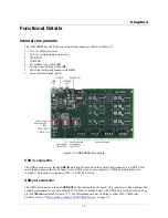
Functional Details
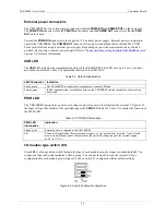
Control logic polarity switch (S2)
Switch
S2
is a four-position switch that sets the control logic polarity for each module group for either inverted
(active high) or non-inverted (active low, default). You can use
Insta
Cal to read the current logic configuration
for each module group.
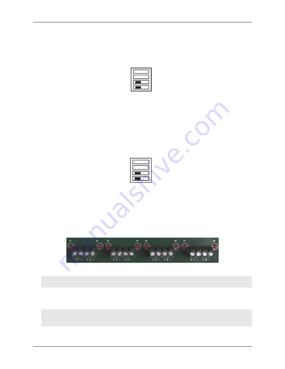
shows switch S2 configured with its default settings.
Figure 3-3
Figure 3-3. Switch S2 default configuration
CH
CL
INVERT
NON
INVERT
S2
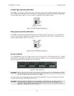
Relay power-up state switch (S3)
Switch
S3
is a four-position switch that sets the state of the output relays at power-up. You can use
Insta
Cal to
read the current resistor configuration for each module group. Fi
shows switch S3 configured with its
default settings (modules inactive on power-up).
gure 3-4
Figure 3-4. Switch S3 default configuration
CH
CL
P/DN
P/UP
S3
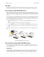
Screw terminals
The USB-SSR08 has eight screw terminal pairs to connect external devices to the SSR modules. Two terminals
are dedicated to each module (one positive and one negative terminal). Each screw terminal is identified with a
label on the board and on the underside of the enclosure lid.
Figure 3-5. Screw terminals
Caution!
Before connecting wires to the screw terminals, turn off the power to the USB-SSR08, and make
sure that the signal wires do not contain live voltages.
Use 12-22 AWG wire for your signal connections. Properly insulate the wires to avoid any short circuit to the
other channels, ground, or other points on the board.
Caution!
Keep the length of stripped wire at a minimum to avoid a short to the enclosure!
When
connecting your field wiring to the screw terminals, use the strip gage on the terminal strip, or
strip to 5.5 - 7.0 mm (0.215" to 0.275") long.
3-3
Содержание USB-SSR08
Страница 1: ......
Страница 6: ...USB SSR08 User s Guide Main connector 4 3 Screw terminal pin out 4 3 v ...

