USB-5106 User's Guide
Functional Details
8
External sensor inputs
Use these 2.5 mm jacks to connect up to four sensors; see
on page 11 for more
information about which sensors are supported.
LCD Screen
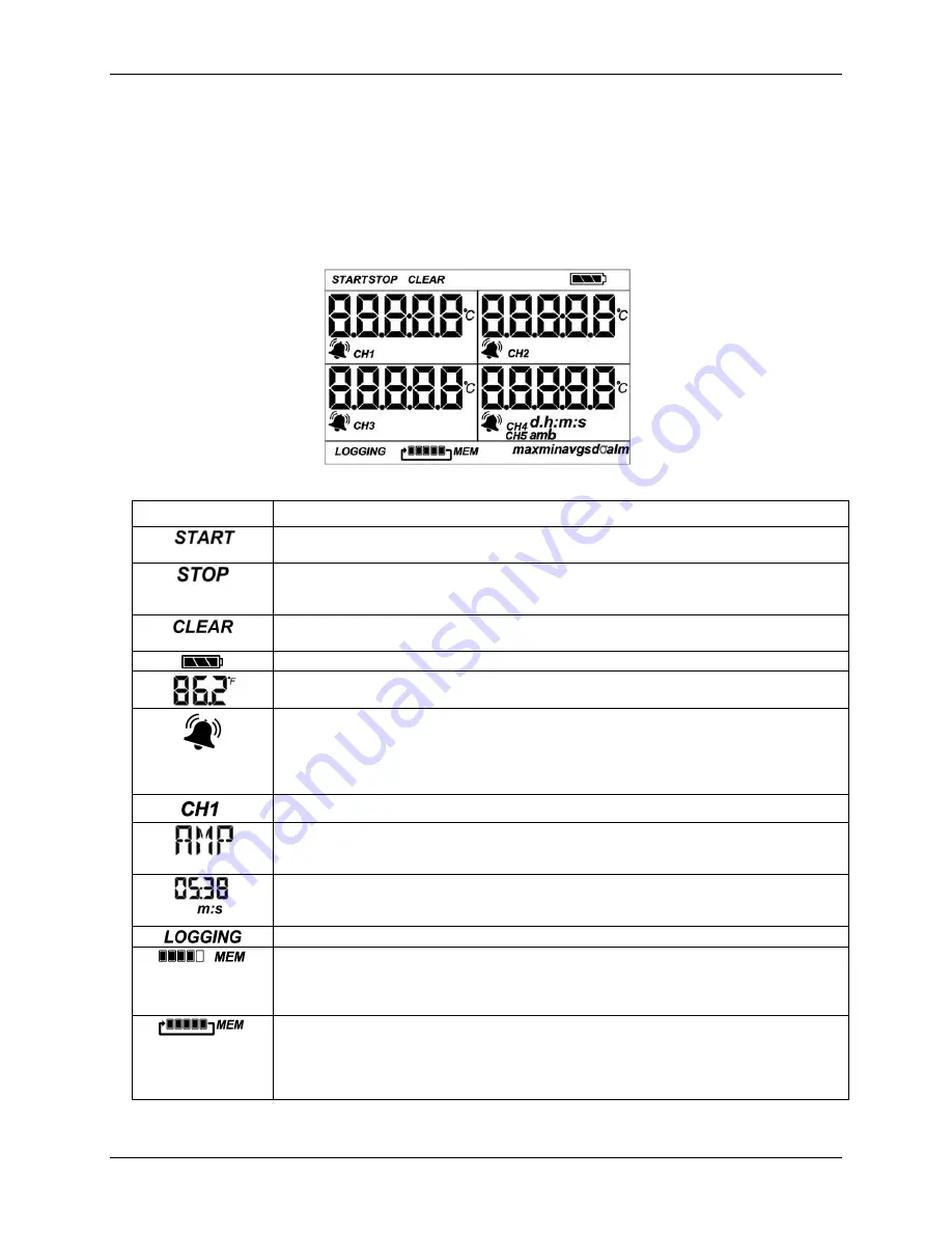
The logger LCD screen displays details about the current status. Figure 2 shows all of the symbols that display
on the LCD screen. The table below lists a description for each symbol.
Figure 2. LCD screen symbols
Symbol
Description
The logger is waiting to be launched. Press and hold the Start/Stop button for 3 seconds to launch
the logger.
The logger was launched with push button stop enabled; press and hold the Start/Stop button for
3 seconds to stop the logger.
Note
: If you also launched the logger with a push button start, this
symbol does not appear on the display for 30 seconds.
An alarm is ready to be cleared. This symbol appears when
Cleared with button press
is
selected in the alarm settings. Press the Alarm/Stats button for 3 seconds to clear the alarm.
The battery indicator shows the approximate battery power remaining.
Sensor reading. An example of a temperature reading is shown here. Temperature units are set with
the software. You cannot change the temperature unit after the logger is launched.
A sensor reading is above or below the configured high or low alarm. Press and release the
Alarm/Stats button until
alm
displays (explained below).
The alarm symbol clears depending on how alarms are configured. If the alarm is configured to
clear when the logger is relaunched, this symbol remains on the LCD. Otherwise, it clears when the
sensor reading is back within the alarm limits or you press the Alarm/Stats button for 3 seconds.
The channel number associated with the sensor reading. Up to four channels are visible at one time.
The sensor unit which appears to the right of the channel number. Enter up to 3 characters with
software for the unit. See
Setting up the Logger
for more details. Note that the unit for temperature
sensors displays as °F or °C only.
The logger is configured to start logging on a particular date/time. The display counts down in
days, hours, minutes, and seconds until logging begins. In this example, 5 minutes and 38 seconds
remain until logging begins.
Displays when the logger is currently logging.
The logger is configured to stop logging when memory fills. The memory bar indicates the
approximate space remaining in the logger to record data. When first launched, all five segments in
the bar are empty. In this example, the logger memory is almost full (only one segment in the
memory bar is empty).
The logger is configured to never stop logging (wrapping). The logger continues recording data
indefinitely, with newest data overwriting the oldest data. When first launched, all five segments in
the memory bar will be empty. In this example, the memory is full (all five segments are filled in)
and new data is overwriting the oldest data. This continues until the logger is stopped or the battery
runs out.


