91
namely ordinary vacuum drying and special
vacuum drying.
1
Ordinary vacuum drying
When conduct first vacuum drying,
connect pressure gauge to the infusing
mouth of gas pipe and liquid pipe, and
keep vacuum pump running for 1hour
(vacuum degree of vacuum pump shall be
reached -755mmHg).
If the vacuum degree of vacuum pump
could not reach -755mmHg after 1 hour of
drying, it indicates that there is moisture or
leakage in pipeline system and need to go
on with drying for half an hour.
If the vacuum degree of vacuum pump still
could not reach -755mmHg after 1.5 hours
of drying, check whether there is leakage
source.
Leakage test: After the vacuum degree
reaches -755mmHg, stop vacuum drying
and keep the pressure for 1 hour. If the
indicator of vacuum gauge does not go up,
it is qualified. If going up, it indicates that
there is moisture or leak source.
2
Special vacuum drying
The special vacuum drying method shall be
adopted when:
Finding moisture during flushing refrigerant
pipe.
Conducting construction on rainy day,
because rain water might penetrated into
pipeline.
Construction period is long, and rain water
might penetrated into pipeline.
Rain water might penetrate into pipeline
during construction.
Procedures of special vacuum drying are as
follows:
Vacuum drying for 1 hour.
Vacuum damage, filling nitrogen to reach
0.5Kgf/cm2 .
Because nitrogen is dry gas, vacuum
damage could achieve the effect of
vacuum drying, but this method could not
achieve drying thoroughly when there is
too much moisture. Therefore, special
attention shall be drawn to prevent the
entering of water and the formation of
condensate water.
Vacuum drying again for half an hour.
If the pressure reaches -755mmHg,start
to pressure leakage test. If it cannot reach
the value, repeat vacuum damage and
vacuum drying again for 1 hour.
Leakage test: After the vacuum degree
reaches -755mmHg, stop vacuum drying
and keep the pressure for 1 hour. If the
indicator of vacuum gauge does not go up,
it is qualified. If going up, it indicates that
there is moisture or leak source.
Additional refrigerant charge
After the vacuum drying process is carried
out, the additional refrigerant charge
process needs to be performed.
The outdoor unit is factory charged with
refrigerant.
The
additional
refrigerant
charge volume is decided by the diameter
and length of the liquid pipe between indoor
and outdoor unit. Refer the following
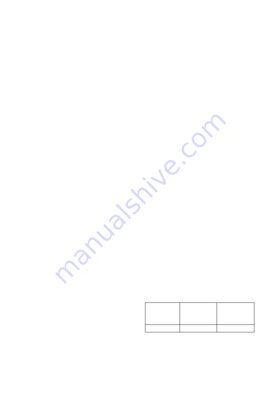
formula to calculate the charge volume.
Diameter
of
liquid
pipe
(mm)
Φ6.35
Φ9.52
Formula
V=15g/m×(L-7.5)
V=30g/m×(L-7.5)
V:
Additional refrigerant charge volume (g).
L:
The length of the liquid pipe (m).
Note:
Содержание CCA3U-09HRFN1-MC
Страница 8: ...5 2 2 Part names of Indoor Outdoor units Cassette Units ...
Страница 9: ...6 A5 Duct Units A6 Duct Units ...
Страница 10: ...7 Console Units ...
Страница 11: ...8 Ceiling floor Units ...
Страница 12: ...9 HESP DUCT Units ...
Страница 31: ...28 Console Units 16 Drain pipe 195 Hanging arm Unit mm 700 600 210 ...
Страница 38: ...35 Console Units Ceiling floor Units ...
Страница 43: ...40 CFAU 09HRFN1 M C CFAU 12HRFN1 M C MCD 36HRFN1 M C MCD 48HRFN1 M D ...
Страница 44: ...41 CTBU 36HWFN1 M C CTBU 48HWFN1 M C ...
Страница 45: ...42 MUEU 18HRFN1 M C MUEU 24HRFN1 M C MUE 36HRFN1 M C ...
Страница 46: ...43 MUE 48HRFN1 M C MUE 60HRFN1 MW ...
Страница 47: ...44 MUE 36HRFN1 M C MUE 48HRFN1 M C ...
Страница 48: ...45 MUE 60HRFN1 MW MTI 18HWFN1 MT0W MTIU 24HWFN1 MW ...
Страница 49: ...46 MTIU 36HWFN1 MW MTIU 48HWFN1 MW MHG 60HWFN1 MW ...
Страница 51: ...48 MOBA30 09HFN1 MT0W MOB30 12HFN1 MT0W ...
Страница 52: ...49 MOD30 24HFN1 MT0W MOD01 23HFN1 MT0W ...
Страница 53: ...50 MOD30U 36HFN1 M ...
Страница 59: ...56 CTBU 09HWFN1 M C Code 0 Code 1 Code 2 Code 3 Code 4 ...
Страница 60: ...57 CTBU 12HWFN1 M C Code 0 Code 1 Code 2 Code 3 Code 4 ...
Страница 61: ...58 CTBU 18HWFN1 M C Code 0 Code 1 Code 2 Code 3 Code 4 ...
Страница 62: ...59 CTBU 24HWFN1 M C Code 0 Code 1 Code 2 Code 3 Code 4 ...
Страница 63: ...60 CTB 36HWFN1 M C Code 0 Code 1 Code 2 Code 3 Code 4 ...
Страница 64: ...61 CTB 48HWFN1 M C Code 0 Code 1 Code 2 Code 3 Code 4 ...
Страница 74: ...71 12 Field Wiring 36K 48K 60K ...
Страница 123: ...120 P U P V ...
Страница 124: ...121 P W P N ...
Страница 141: ...138 ...
Страница 151: ...148 4 Remove the evaporator support board 5 Screw off the fixing screws to remove the evaporator 4 screws 1 screw ...
Страница 187: ...184 5 Remove the four fixing screws of the fan motor then remove the motor 5 ...
Страница 200: ...197 6 Remove the grounding screw 7 Remove the Wires 1 2 3 or L1 L2 S Then remove the electronic control box 7 ...


