SimStep
Manual - 3400 Iss. D
7
th
June 2004
page 4
The PM600 position controller generates the
clock
and
direction
signals for the MSE570
drive in response to move commands.
The PM600
enable
output is connected to the
enable
input of the MSE570 drive. If the
PM600’s
enable
output is turned off (e.g. as a result of an error) the motor current will
turned off. The
enable
output may be turned off by an
AB
abort
command, or
reset
(turned
on) by an
RS
command (see Section 6.4).
The
Idle
output from the PM600 is connected to the
current reduction
input on the
MSE570 to reduce the motor current to about 25% when the motor is not moving.
An incremental encoder can be fitted to the motor or mechanism to monitor the movement
of the mechanism. The quadrature signals from the encoder are connected to the PM600
to allow passive closed-loop operation. The system is initially supplied with the PM600
configured for open-loop operation. The PM600 must be reconfigured for closed-loop
operation (see Section 8.2).
The MSB867 has a multi-axis jog receiver; it allows the PM600’s Jog inputs to be
controlled by a JC809 Jog Box. The axis addresses shown on the JC809 may be
changed by altering the settings of the rotary switches accessible by removing the top
cover of the unit.
The power supply pr24V (nominal) to energise the supply rail on the PM600
controller, and +40V (nominal) to energise the supply rail on the MSE570 drive.
The PM600 manual referred to in this document can be found on
www.mclennan.co.uk
.
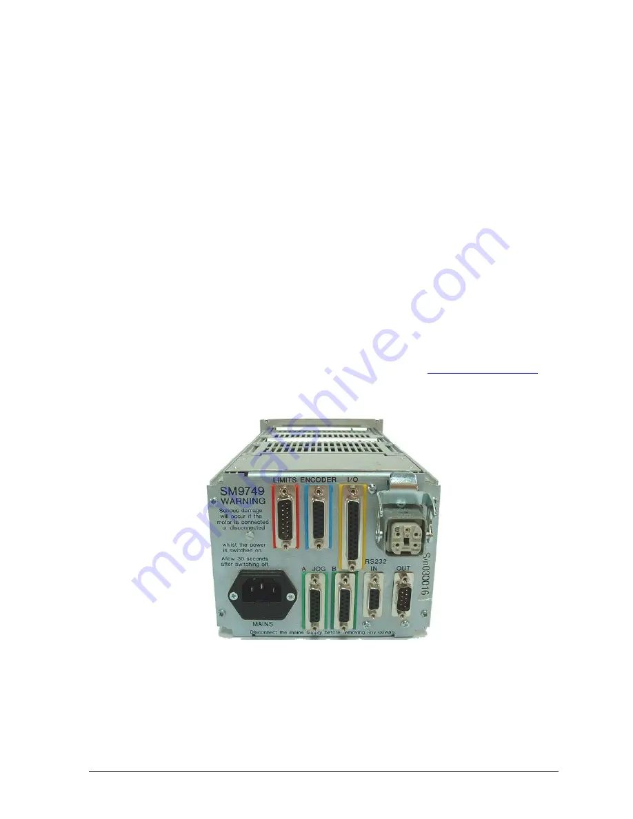
1.1 Rear View:
Fig.1.2
SimStep
Rear Panel
Connections for motors, limits/datum, I/O, encoders, RS232 and mains are taken from the
MSB867 backplane to connectors on the rear panel.


