background image

Electrical Connections


Operation of dryers with improper line voltage constitutes 

abuse and could affect the dryer warranty.

The dryers are constructed according to NEMA Type 1 electrical 

standards. Field wiring must comply with local and national fire, 

safety and electrical codes. Installation must be in accordance 

with the National Electrical Code. Confirm that your line voltage 

is the same as the voltage listed on the dryer data plate. Refer 

to Figure 5 electrical schematics.

HOW IT WORKS

Phase Change Mechanism of the FLEX Dryer 

1.  When the refrigeration compressor and the condenser fan 

are running, the cold refrigerant in the chiller (evaporator) 

cools the liquid Phase Change Material (PCM) which gradu-

ally solidifies.

2.  When the PCM is sufficiently cooled and solidified, the 

refrigeration compressor and condenser fan will stop.

3.  The compressed air is continuously cooled by the PCM 

while the refrigeration compressor is inactive. No power 

is consumed during this period.

4.  The PCM gradually liquefies as it adsorbs heat from the 

compressed air, and when fully melted, the refrigeration 

compressor and condenser fan resume to cool the PCM.

Compressed Air flow 

The dryers use refrigeration cooling to condense entrained 

moisture out of the air stream. Warm saturated air enters the 

air-to-air heat exchanger where it is cooled by outgoing cold 

air. The inlet air is further cooled in the refrigeration chiller. The 

condensate is removed from the air stream by an electronic 

drain valve.
The cold, dry air is reheated by incoming warm air as it passes 

back through the air-to air heat exchanger. Using the outgo-

ing air to pre-cool the inlet air condenses up to 65 percent of 

the moisture out of the inlet air before it reaches the chiller. 

Pre-cooling the inlet air reduces the heat load on the refriger-

ant compressor, permitting the use of a smaller refrigerant 

compressor.

Figure 2. 

Schematic diagram of the compressed air flow and 

refrigerant

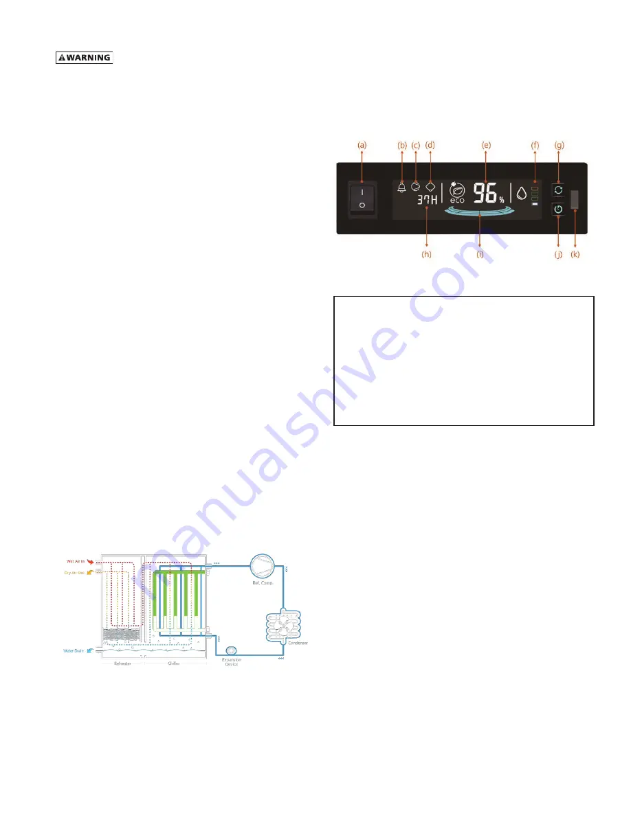
CONTROLLER

The controller provides ease of monitoring and operating 

status for Energy Savings (%), dryer operating time, refrigera-

tor compressor operating time, and active fault message dew 

point status. The controller also provides advanced functions 

like communication and operating status data storage.

Figure 3.

Controller

a:  DRYER ON/OFF SWITCH
b:  ALARM LIGHT
c:  REFRIGERANT COMPRESSOR RUNNING LIGHT
d:  DRYER RUNNING LIGHT
e:  ENERGY SAVING RATIO (%)
f:  DEWPOINT TEMPERATURE INDICATOR
g:  RUNNING TIME SELECT BUTTON
h:  DRYER RUNNING / REFRIGERANT COMPRESSOR RUNNING TIME
i:  ENERGY SAVING (GRAPH)
j:  TIMER BUTTON

 (LEVEL 2 ONLY)

k:  MICRO-USB CONNECTION PORT

 (LEVEL 2 ONLY)

Controller Functions

1.  Dryer On/Off 
2.  Display energy saving ratio (%)
3.  Display alarm signal
4.  Display dryer and refrigerant compressor running time
5.  Display dew point level by indicator
6.  Save the operating data

a.  Refrigerant compressor on/off status, Alarm, Dew 

point level, Inlet air temperature

b.  Memory chip can save maximum 30 days

c.  When there is no space to save, then erase the first 

one

7.  MICRO-USB connection port

a.  Automatically download operating data

b.  Automatically upgrade firmware program

8.  Communication port

a.  RS485: Modbus monitoring

MCGUIRE AIR COMPRESSORS INC

1-888-229-9999

MCGUIRE AIR COMPRESSORS INC

1-888-229-9999

Содержание SPXFLOW FLEX DFX 12.5

Страница 1: ...FX 12 5 DFX 15 1 DFX 20 1 FOR M NO 7473076 R EVI S ION 08 2019 R EAD AN D U N D E R STAN D TH I S MAN UAL PR IOR TO OPE RATI NG OR S E RVICI NG TH I S PROD UCT I N STR UCTION MAN UAL MCGUIRE AIR COMPR...

Страница 2: ...7 DRAWINGS General Arrangement Model DFX 8 1 8 Models DFX 12 5 DFX 15 1 9 Model DFX 20 1 10 Electrical Schematic 11 Air and Refrigerant Flow Schematic Model DFX 8 1 12 Models DFX 12 5 DFX 15 1 DFX 20...

Страница 3: ...ity have the potential to cause personal injury or equipment damage Before doing any work on the dryer be sure the electrical supply has been locked and tagged and the internal pressure of the dryer h...

Страница 4: ...ittings must be rated for the maximum operating pressure given on the dryer data plate and must be in accor dance with applicable codes Support all piping do not allow the weight of any piping to stre...

Страница 5: ...ated by incoming warm air as it passes back through the air to air heat exchanger Using the outgo ing air to pre cool the inlet air condenses up to 65 percent of the moisture out of the inlet air befo...

Страница 6: ...omponent of the compressed air system under pressure may cause equipment failure and serious personal injury Operation 1 To start the dryer turn on the a dryer on off switch 2 When the refrigeration c...

Страница 7: ...HA approved air nozzle that limits its discharge pressure to 30 psig 2 1 kgf cm2 Yearly Maintenance It is recommended to replace the drain service unit annually For units purchased with a filtration p...

Страница 8: ...let air temperature too high Reduce aftercooler discharge temperature to design conditions See Engineering Data Tables Excessive airflow Check airflow and system capacity Reduce airflow or resize and...

Страница 9: ...Setting cut in cut out 217 5 275 6 psig 15 19 barg Electrical Data Nominal Voltage 460 3 60 Input Power Rated Flow watts 4 300 7 600 9 000 10 000 Minimum Circuit Ampacity 9 8 16 5 16 9 20 4 Maximum Ov...

Страница 10: ...92 760 31 50 800 58 59 1488 3 94 100 54 02 1372 50 08 1272 3 ANSI Flange 1133 514 HOLE FOR MAIN POWER DRAIN OUTLET 4 10 MOUNTING HOLES FOOT PRINT H G C F A B E J VENT DRAIN VALVE D WETTED AIR INLET D...

Страница 11: ...1350 4 ANSI Flange 1537 697 DFX 15 1 10 85 276 19 69 500 6 09 155 37 80 960 39 37 1000 58 59 1488 3 94 100 57 09 1450 53 15 1350 4 ANSI Flange 1766 801 HOLE FOR MAIN POWER DRAIN OUTLET 4 10 MOUNTING H...

Страница 12: ...09 155 37 80 960 39 37 1000 58 59 1488 3 94 100 63 78 1620 59 84 1520 4 ANSI Flange 2028 920 HOLE FOR MAIN POWER DRAIN OUTLET 4 10 MOUNTING HOLES FOOT PRINT H G A B F E C J D VENT DRAIN VALVE TOPVIEW...

Страница 13: ...SW 2 3 4 T R S MC1 COMP 0V 480V 0V 120V 460V 3PH 60HZ W1 U1 V1 E 2 1 MAIN POWER TH1 AC IN COMP ALARM DRAIN COM ON R1 S1 FG S2 R2 COM ON COM N C N 0 TS3 TS2 DRAIN TRAP 24 21 12 25 20 30 TS1 DRAIN TRAP...

Страница 14: ...VE DRAIN OUTLET NO LOSS VALVE EXPANSION DEVICE TEMP SENSOR2 TS2 SEPARATOR FILTER TEMP SENSOR3 TS3 MANUAL REFRIGERANT COMPRESSOR CONDENSER COOLING AIR FLOW AIR COOLED FILTER CONDENSER AIR COOLED HIGH P...

Страница 15: ...OOLED TEMP SENSOR2 TS2 TEMP SENSOR3 TS3 FILTER CONDENSER AIR COOLED HEAT EXCHANGER AIR AIR REF PCM AIR REHEATER CHILLER BRAZED PLATE HEAT EXCHANGER BRAZED PLATE DRAINVALVE DRAIN OUTLET NO LOSS VALVE S...

Страница 16: ...06 Separator 7473007 7473008 7473008 7473009 White Temperature Sensor 7440388 7440388 7440388 7440388 Red Temperature Sensor 7440389 7440389 7440389 7440389 Yellow Temperature Sensor 7440390 7440390 7...

Страница 17: ...15 NOTES MCGUIRE AIR COMPRESSORS INC 1 888 229 9999 MCGUIRE AIR COMPRESSORS INC 1 888 229 9999...

Страница 18: ...MCGUIRE AIR COMPRESSORS INC 1 888 229 9999 MCGUIRE AIR COMPRESSORS INC 1 888 229 9999...

Страница 19: ...manufacturer s product The maximum damages liability of the manufacturer is the original purchase price of the product or part THE FOREGOING WARRANTY IS EXCLUSIVE AND IN LIEU OF ALL OTHER WARRANTIES W...

Страница 20: ...vements and research are continuous at SPX FLOW Inc Specifications may change without notice ISSUED 08 2019 Form No 7473076 Revision None COPYRIGHT 2019 SPX FLOW Inc FLEX Series Refrigerated Type Comp...

Отзывы: