2
Ambient Air Temperature
Locate the dryer indoors where the ambient air temperature will
be between 39°F (4°C) and 122°F (50°C). Intermittent operation
at ambient temperatures up to 122°F (50°C) will not damage the
dryer but may result in a higher dew point or dryer shutdown
due to high refrigerant discharge pressure (see Field Service
Guide). Call your local distributor if prolonged operation at
ambient temperatures above 122°F (50°C) or below 39°F (4°C)
is unavoidable.
Do not operate air-cooled dryers at ambient air temperatures
below 39°F (4°C). Such operation may result in low suction pres-
sure, causing freeze-up.
Location and Clearance
Mount the dryer on a level base and bolt down if the base vi-
brates. If the dryer is air cooled, install it in a clean, well-ventilated
area to reduce fouling of the condenser coils with dirt and dust.
Allow 48 inches (1220 mm) clearance on the sides and the front
of the dryer for cooling airflow and service access.
System Arrangement
Liquid water adversely affects dryer performance. To prevent
“slugging” the dryer with liquid water, locate the dryer down-
stream of an aftercooler and a mechanical separator. Install
drain valves to discharge condensate that collects in these areas.
If the airflow is relatively constant and will not cause short term
overloading of the dryer, it is recommended that the dryer be
located downstream of the receiver tank. If the nature of the
application is such that the air demand regularly exceeds the
dryer flow rating, it is recommended that the dryer be located
upstream of the receiver.
For safety and convenience, install inlet and outlet shutoff
valves and depressurization valves at the locations indicated.
These valves allow the dryer to be isolated and depressurized
for servicing. Bypass piping may be installed around the dryer
for uninterrupted airflow when the dryer is serviced. If the com-
pressed air operation cannot tolerate wet air for short periods,
install a second dryer in the bypass line.
Compressed air systems commonly require filters to remove
compressor oils, particulates, condensed liquids and other
contaminants. When an oil-removal filter is used, install the
filter downstream of the dryer. At this location, the life of the
replaceable filter element is prolonged since the dryer removes
some of the entrained oil and drained through the separator.
Piping and Connections
The user must furnish piping unless otherwise specified. Con-
nections and fittings must be rated for the maximum operating
pressure given on the dryer data plate and must be in accor-
dance with applicable codes. Support all piping; do not allow
the weight of any piping to stress the dryer or filters. Inlet and
outlet shutoff valves and bypass valves are recommended. Pip-
ing should be at least the size of the inlet and outlet connections
to minimize pressure drop in the air system. See Specification
Table for dryer inlet and outlet connections.
Drains
Condensate must be drained from the dryer to prevent an influx
into outlet air. The FLEX dryers are equipped with an automatic
no loss drain valve and internal drain hoses up to the drain con-
nections on the dryer cabinets.
The user must install a discharge line from the drain connection
and run it to a waste disposal collection system that meets ap-
plicable regulations. Pipe or copper tubing 1/2 inch or larger is
recommended for condensate discharge lines. Install the drain
lines so that condensate can be seen as it drains.
NOTE:
Discharge is at system pressure. Drain line should be
anchored.
NOTE:
Condensate may contain oil. Comply with applicable laws
concerning proper disposal.
Drain Valve Operation
A. Verify that isolation valves are open. If the drain fails to
discharge after the valve is energized, the electronic control
circuit will repeatedly energize the valve in an attempt to
clear the discharge port. If, after 60 seconds, the drain still
fails to discharge, the control circuit then switches to the
alarm mode. In this mode the valve is de-energized and the
red alarm light is activated on the drain. The valve is then
automatically energized every 4 minutes for 5 seconds.
Check the drain operation. Push drain (push-to-test) button
on the drain or the Electronic Controller (if equipped) to
energize drain. A flow of condensate and/or air should be
present at the drain outlet. The alarm mode automatically
clears after the drain returns to normal operation.
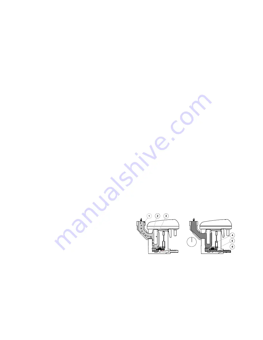
B. The condensate flows through the feed line
(1)
into the
condensate drain and accumulates in the housing
(2)
. A
capacitive sensor
(3)
continuously registers the liquid level.
As soon as the container is filled, a fixed waiting period
begins during which more condensate accumulates. After
the waiting time has expired the pilot valve (4) is then ac-
tivated and the diaphragm
(5)
opens the outlet line
(6)
for
discharging the condensate.
When the condensate drain has been emptied, the outlet
line is closed again quickly and tightly without wasting
compressed air.
Figure 1.
Schematic diagram of the no loss drain valve
MCGUIRE AIR COMPRESSORS INC
1-888-229-9999
MCGUIRE AIR COMPRESSORS INC
1-888-229-9999


