McFarlane HDL-1000 Series Скачать руководство пользователя страница 32

APPENDIX B 

32

HDL-1024 through HDL-1038 HARROW CART 

PARTS DIAGRAM  


Содержание HDL-1000 Series

Страница 1: ...THOROUGHLY To obtain the best performance of the unit familiarize yourself with each component and adjustment Store this manual where it can be readily available for future reference In the event tha...

Страница 2: ...LOWING OPERATION 9 HIGHWAY AND TRANSPORT OPERATIONS 9 10 PERFORMING MAINTENANCE 10 MAINTENANCE AND SERVICE SCHEDULE 11 OPERATING SUGGESTIONS 11 ASSEMBLY SUGGESTIONS 12 ASSEMBLY INSTRUCTIONS 13 28 FINA...

Страница 3: ...or have questions concerning these or other applications LIMITED WARRANTY FULL ONE YEAR WARRANTY OF HDL 1000 Series If within one year from the date of purchase this transport cart and or its accompa...

Страница 4: ...WORDS Note the use of the signal words DANGER WARNING and CAUTION with the safety messages The appropriate signal word for each has been selected using the following guidelines DANGER Indicates an imm...

Страница 5: ...require additional copies or the manual is damaged please contact your local dealer or McFarlane Mfg Co Inc 1330 Dallas Street P O Box 100 Sauk City WI 53583 PHONE 608 643 3321 TOLL FREE 800 627 8569...

Страница 6: ...s Do not allow persons to operate or assemble this unit until they have read this manual and have developed a thorough understanding of the safety precautions and of how it works To prevent injury use...

Страница 7: ...e is any portion of this manual or function you do not understand contact your local authorized dealer or the manufacturer Before Operation Carefully study and understand this manual Do not wear loose...

Страница 8: ...hear people shouting NO PASSENGERS ALLOWED Do not carry passengers anywhere on or in the tractor or equipment except as required for operation Keep hands and clothing clear of moving parts Do not cle...

Страница 9: ...to a minimum Reduce speed prior to turns to avoid the risk of overturning Avoid sudden uphill turns on steep slopes Always keep the tractor or towing vehicle in gear to provide engine braking when goi...

Страница 10: ...ak on attachments Use a piece of cardboard or wood Hydraulic fluid escaping under pressure can penetrate the skin Openings in the skin and minor cuts are susceptible to infection from hydraulic fluid...

Страница 11: ...be towed at speeds ranging from six to nine 6 9 mph This keeps the field debris moving through the harrow sections and avoids clogging The best results will be obtained after the paint has been scour...

Страница 12: ...he position the harrows would be in when the unit is being transported from place to place that is with the harrows up and the wings folded and secured in the wing rests When assembling this unit make...

Страница 13: ...frame Axle Brackets Be sure the valve stem is pointing away from the Axle Bracket 5 Attach the jack to the A frame Figure 1 6 Assemble either a clevis hitch Figure 2 or a pintle hitch Figure 3 as requ...

Страница 14: ...to the square frame Refer to Figure 4 Use four 5 8 x 6 x 5 U bolts lock washers and hex nuts Do not tighten yet The distance D in Figure 4 from square frame splice plate to the wing rest mounting plat...

Страница 15: ...he square frame behind the splice plates HDL 1040 HDL 1042 through HDL 1046 HDL 1052 through HDL 1060 22 6 55 SQUARE FRAME WING REST D WITH CLAMP PLATES LOCK WASHERS AND HEX NUTS 5 8 x 5 BOLTS Attach...

Страница 16: ...bar using two 1 x 8 5 16 hinge pins and the x 3 grade 8 bolts and locking hex nuts Note the location of the wing cylinder posts figure 6 and the orientation of the wing axle mount plate figure7 Attac...

Страница 17: ...not over tighten 2 Attach the two similar male tees the ones without an o ring fitting to the hydraulic tee bracket in the middle of the square frame using the tee nuts 3 Attach the two hoses from the...

Страница 18: ...er to the parts diagram in appendix B Do not over tighten 3 Attach the cylinders to the cylinder posts on the center bar and wings 4 Attach two hoses to each of the 3 8 elbows in the wing cylinders 5...

Страница 19: ...Persons assembling an 8 12 or 16 bar harrow should ignore the instructions in italics describing the attachment of the rear pull points Those assembling a dual section harrow should be sure to follow...

Страница 20: ...etween each of the lift arm pull points 10 link for 8 bar harrow sections 8 link for all other configurations Use x 2 bolts lock washers and hex nuts Refer to Figure 11 4 Bolt an 8 link lift chain bet...

Страница 21: ...x 3 bolt and lock nuts Refer to Figure 13 6 Bolt an 8 link pull chain to the end of the rear pull point assembly with a x 2 bolt lock washer and hex nut Refer to Figure 13 This chain will connect to...

Страница 22: ...ar application Refer to Figure 15 to help clarify what is meant by angle of attack McFarlane flexible harrow sections have a built in system which allows the harrow owner a choice between a steep or s...

Страница 23: ...x C to determine the placement of the harrow sections HEX NUT LOCK WASHER HARROW PULL TAB FLAT WASHER 1 2 X 1 1 2 BOLT Figure 16 Instructions follow for attaching the harrow sections Be sure to follow...

Страница 24: ...ottom of the pull tabs 2 Bolt the front and rear harrow sections together using two 5 16 x 1 x 6 dual section connector links at each pull tab Refer to Figure 18 Use two x 2 bolts lock washers and hex...

Страница 25: ...FLAT WASHERS LOCK WASHERS AND HEX NUTS FRONT SECTION REAR SECTION LIFT ARM Figure 19 Connect 4 4 6 6 or 8 8 Sections 1 Bolt the pull chains to the front tabs on the harrow sections Refer to Figures 1...

Страница 26: ...the center bar Rotate the harrow sections down into the field position 2 Pin one end of a wing cable to the tab on the side of the A Frame as shown in Figure 20 Use one 1 x 2 clevis pin and 3 16 x 2 c...

Страница 27: ...e lift angle Use the lock clips and 7 16 x 1 1 2 bolts with lock nuts 4 Attach the 1 4 x 7 link lift chain to the cable lift angle with a 5 16 shackle shackle pin and cotter pin 5 Adjust the assembly...

Страница 28: ...the clevis on the main frame cylinder in out to move the wings up down Adjust the stop bolt tight against main hinge plate when the unit is in the transport position and secure with the jam nut Main...

Страница 29: ...ctors should be visible from the front of the unit 5 Do not detach the unit from the tractor unless the jack stand is down and the wings are secured in the wing rests 6 After the first few hours of op...

Страница 30: ...ic restrictors Wings will not slide into wing rests Wing rests improperly positioned Reposition wing rests Main hinge plate stop bolt maladjusted Readjust hinge plate stop bolt Excessive clogging duri...

Страница 31: ...10 1 4 28 14 7 10 5 16 18 22 3 15 2 5 16 24 23 4 18 4 3 8 16 39 28 3 8 24 41 30 7 16 14 60 44 7 16 20 60 44 1 2 13 88 63 1 2 20 98 70 9 16 12 134 98 9 16 18 134 98 5 8 11 172 127 5 8 18 176 127 3 4 1...

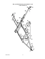
Страница 32: ...APPENDIX B 32 HDL 1024 through HDL 1038 HARROW CART PARTS DIAGRAM...

Страница 33: ...hand 1 10 PH 10 CABLE LIFT ARM SPRING 2 11 HDL 2543 CABLE LIFT ARM ANGLE 2 12 DB 125 LOCK CLIP 4 13 CH 1407 CABLE LIFT CHAIN 2 14 AL 030 CABLE LIFT CHAIN ANCHOR SHACKLE 2 15 BU 5865 U BOLT 5 8 x 6 x...

Страница 34: ...12 WING HINGE PIN 8 5 16 4 38 WING FRAME see layout diagram for part number 1 39 HDL 2750 WING CABLE BRACKET left hand 1 HDL 2751 WING CABLE BRACKET right hand 1 40 HDL 2752 WING CABLE BRACKET CLAMP P...

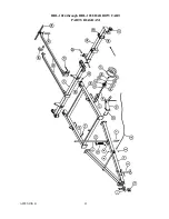
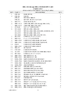
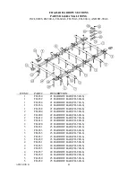
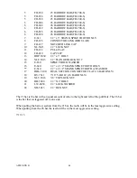
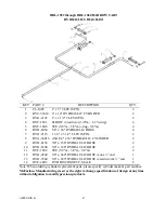
Страница 35: ...APPENDIX B 35 HDL 1040 THROUGH HDL 1050 HARROW CART PARTS DIAGRAM...

Страница 36: ...COTTER PIN 4 14 WC 2190 WING CABLE HDL 1040 TO 1046 2 WC 2202 WING CABLE HDL 1048 HDL 1050 2 15 HDL 2521 WING REST CLAMP PLATE 2 16 HDL 2520 WING REST 8 LT 1 HDL 2528 WING REST 8 RT 1 17 WDL 2500 MAI...

Страница 37: ...FRAME see layout diagram for part number 1 39 HDL 2750 WING CABLE BRACKET left hand 1 HDL 2751 WING CABLE BRACKET right hand 1 40 HDL 2752 WING CABLE BRACKET CLAMP PLATE 2 41 SAME AS ITEMS 17 THROUGH...

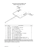
Страница 38: ...APPENDIX B 38 HDL 1052 THROUGH HDL 1060 HARROW CART PARTS DIAGRAM...

Страница 39: ...2288 WING CABLE HDL 1052 to 1060 2 15 HDL 2521 WING REST CLAMP PLATE 2 16 HDL 2520 WING REST 8 LT 1 HDL 2528 WING REST 8 RT 1 17 WDL 2500 MAIN AXLE BRACKET 2 WDL 2506 MAIN FRAME WALKING AXLE BRACKET...

Страница 40: ...MS 17 THROUGH 26 2 DC 111 DECAL STAND CLEAR 1 DC 116 DECAL DO NOT CLIMB ON 1 DC 117 DECAL USE JACK STAND 1 DC 119 DECAL ESCAPING FLUID 1 HY 0340 HYDRAULIC BAG HDL 1052 through 1060 1 HB 0312 FRAME HAR...

Страница 41: ...FH 500 8 2 FH 806 2 HARROW BAR FH 600 8 2 FH 810 2 HARROW BAR FH 700 8 2 FH 814 2 HARROW BAR FH 800 8 2 FH 818 2 HARROW BAR FH 900 8 3 FH 802 3 HARROW BAR FH 500 8 3 FH 806 3 HARROW BAR FH 600 8 3 FH...

Страница 42: ...8 FH 820 8 HARROW BAR FH 900 8 9 E 611 x 3 SHANK SPIKE TOOTH ONLY 10 FH 125 CONNECTOR LINK REGULAR 11 FH 127 NOTCHED LINK CAP 12 1 2 LOCK NUT 13 FH 122 PULL FLAT 14 FH 019 CAP CLIP 15 x 3 BOLT 16 FLA...

Страница 43: ...OW BAR FH 500 6 2 FH 808 2 HARROW BAR FH 600 6 2 FH 812 2 HARROW BAR FH 700 6 2 FH 816 2 HARROW BAR FH 800 6 2 FH 820 2 HARROW BAR FH 900 6 3 FH 831 3 HARROW BAR FH 500 6 3 FH 833 3 HARROW BAR FH 600...

Страница 44: ...3 1 2 FLANGED LOCK NUT 15 E 630 SPIKE TOOTH WASHER 16 E 620 1 2 x 2 1 2 SHANK SPIKE TOOTH ONLY E 610 1 2 x 2 1 2 SHANK SPIKE TOOTH w WASHER 17 HDL 5100 DUAL SECTION CONNECTOR FLAT 16 BAR ONLY 18 BV 76...

Страница 45: ...CLEVIS PIN 4 8 HYA 33516 ASAE 3 1 2 x 16 HYDRAULIC CYLINDER 2 9 HYH 8084 3 8 x 84 HYDRAULIC HOSE 2 10 HYH 8104 3 8 x 10⁴ HYDRAULIC HOSE 2 11 HYF 1888 TEE 3 8 m 3 8 m 3 8 m 2 12 HYH 9180 3 8 x 180 HYD...

Страница 46: ...0 HYH 8132 3 8 x 132 HYDRAULIC HOSE 2 11 HYF 1888 TEE 3 8 m 3 8 m 3 8 m 2 12 HYH 9204 3 8 x 204 HYDRAULIC HOSE w one end 1 HDL 1040 through HDL 1046 only 12 HYH 9240 3 8 x 240 HYDRAULIC HOSE w one end...

Страница 47: ...x 3 1 2 CLEVIS PIN 2 8 HYA 34016 ASAE 4 x 16 HYDRAULIC CYLINDER 2 9 HYH 8156 3 8 x 156 HYDRAULIC HOSE 2 10 HYH 8180 3 8 x 180 HYDRAULIC HOSE 2 11 HYF 1888 TEE 3 8 m 3 8 m 3 8 m 2 12 HYH 9240 3 8 x 24...

Страница 48: ...APPENDIX C 48...

Страница 49: ...APPENDIX C 49...

Страница 50: ...APPENDIX C 50...

Страница 51: ...APPENDIX C 51...

Страница 52: ...APPENDIX C 52...

Страница 53: ...APPENDIX C 53...

Страница 54: ...APPENDIX C 54...

Страница 55: ...APPENDIX C 55...

Страница 56: ...APPENDIX C 56...

Страница 57: ...APPENDIX C 57...

Страница 58: ...APPENDIX C 58...

Страница 59: ...APPENDIX C 59...

Страница 60: ...APPENDIX C 60...

Страница 61: ...APPENDIX C 61...

Страница 62: ...APPENDIX C 62...

Страница 63: ...APPENDIX C 63...

Страница 64: ...APPENDIX C 64...

Страница 65: ...APPENDIX C 65...

Страница 66: ...Notes...

Страница 67: ...________________Delivery Date________________________ DEALER INSPECTION REPORT SAFETY _______Wheel bolts tight _______All decals installed _______Fasteners tight _______Review operating and safety ins...

Страница 68: ......

Страница 69: ......

Страница 70: ...Dealer Contact Information McFARLANE MANUFACTURING CO INC 1330 DALLAS STREET P O BOX 100 SAUK CITY WISCONSIN 53583 PHONE 608 643 3321 TOLL FREE 800 627 8569 FAX 608 643 3976 WEB www flexharrow com...

Отзывы: