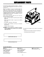
background image

- 4 -

OPERATION

Introduction

This parts manual contains only standard parts.  Variations
of these parts as well as other special parts are not included.
Contact your local MBW distributor for assistance in
identifying parts not included in this manual.

Before Starting & Operating

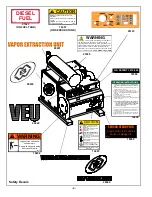
• Operating VEU creates a possible source of ignition for

flammable gas plume.  BE CERTAIN ATMOSPHERE IS
SAFE BEFORE OPERATING THIS MACHINE!

• REMEMBER! It is the owner’s responsibility to

communicate information on the safe use and proper
operation of this unit to the operators.

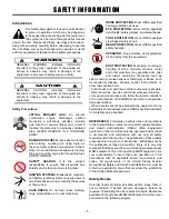
• Review ALL of the Safety Precautions listed on page 1 of

this manual.

• Familiarize yourself with the operation of the machine

and confirm that all controls function properly.

• Know how to STOP the machine in case of an

emergency.

• Make sure hands, feet, and clothing are at a safe

distance from any moving parts or high suction areas.

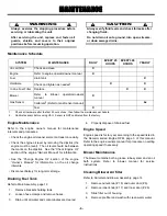
• OIL LEVEL - Check the oil level in the engine.  For more

information see “Lubrication” under the respective
engine’s “Owners Manual” or the Maintenance section of
this manual.

• ENGINE AIR CLEANER - Check to ensure element is in

good condition and properly installed.

• BLOWER AIR CLEANER - Check to ensure element is

in good condition and properly installed

• FUEL SUPPLY - The engines on MBW equipment

require an automotive grade of clean, fresh, diesel fuel.

• FUEL FILTER - If clogged or damaged, replace.

• GAS SENSOR - Be familiar with operation of gas sensor.

Refer to sensor manual.  Be certain that the sensor has
been calibrated and is in working order.  MBW
recommends the sensor be calibrated at least every 3
months.  

Assembling Probes

1.

Place probes into ground

2.

Connect probes to VEU with hose assemblies.

Note

:

  The MBW VEU probes can be connected to the

VEU in many ways.  Each utility should develop

their own best practice to make the connections.
To avoid a significant pressure drop, MBW
recommends not connecting more then 6 (six)
probes to a single 1-1/2” branch hose.  If more
probes are desired, they should be connected to a
new branch line coming off the VEU.

3.

Open all valves on VEU probes.

4.

Cap all open hose ends with CAM-Loc plugs/caps.

5.

Close unused manifold valves on VEU.

6.

Fully open Air-Bypass valve before starting engine.  

Starting Engine

For detailed instructions refer to the engine “Owner’s
Manual”.

WARNING

Ensure gas concentration in work area is safe for
open ignition sources.  DO NOT use machine in
areas that are unsafe.

WARNING

Ensure sampling line and cup are in place at
bottom of sensor.  DO NOT use machine if the
sampling line is not connected.

7.

Plug sensor/vacuum combo plug into socket on
canister housing.

Note: Engine will NOT run without sensor plugged in.

8.

When power is supplied to the sensor stand
assembly the sensor will start a warm up cycle.  

This

cycle will take approximately 4 minutes and
engine will NOT RUN until the “Wait to Start” light
turns off.

9.

Open bypass valve fully, close all vacuum supply
valves on canister, open valves on probes.

10. Turn toggle switch to “ON”.

11. Press glow plug button if engine is cold.  Glow plugs

will cycle each time button is pressed.

12. Press engine start button to engage starter.

13. Allow engine to warm up for one or two minutes.

Operating

1.

Ensure proper operation of gas sensor.

2.

Run engine speed up to approximately 30%.

Содержание VAPOR EXTRACTION UNIT

Страница 1: ...td Units 2 3 CochraneStreet Bolton BL3 6BN England UK Phone 44 0 01204 387784 Fax 44 0 01204 387797 E mail mbwuk btinternet com MBW FRANCE S A R L Phone 33 0 3 44 07 15 96 Fax 33 0 3 44 07 41 28 L1926...

Страница 2: ...Tank 6 Engine Speed 6 Blower Maintenance 6 Cleaning Blower Air filter 6 Sensor Maintenance 7 Sensor Relay Alarm Testing 7 Oiling the blower for long term storage 7 SERVICE 8 Torque Chart 8 Service To...

Страница 3: ...CALIFORNIA PROPOSITION 65 WARNING Engine exhaust and some of its constituents are known in the state of California to cause cancer birth defects and other reproductive harm WARNING...

Страница 4: ...pecified steel tipped safety shoes HEAD PROTECTION Wear OSHA specified safety helmets OPERATOR Keep children and bystanders off and away from the equipment DUST PROTECTION Machining crushing or handli...

Страница 5: ...valve is closed fully run engine as needed to evacuate ground of gas 11 If desired turning off individual probes can help locate leak 12 Before shutting down engine allow it to Idle 1 2 minutes to coo...

Страница 6: ...perating Weight 1430 LBS 648 KG Height 47 5 113 cm Width 43 109 cm Length 65 165cm Engine Isuzu 3CH1 Recommended Engine RPM 2500 rpm Fuel Consumption 1 0 Gal hr Fuel Capacity 8 gallons 30 3L Blower Tu...

Страница 7: ...the sensor be calibrated at least every 3 months Assembling Probes 1 Place probes into ground 2 Connect probes to VEU with hose assemblies Note The MBW VEU probes can be connected to the VEU in many w...

Страница 8: ...See note above Operating point will be determined by these factors Configuration of probes Gas concentration in ground Recommended engine speed Recommended vacuum level 5 After bypass valve is closed...

Страница 9: ...tion on the oil change intervals Disconnect battery for long term storage Draining Fuel Tank Refer to Main Assembly page 12 1 Remove brackets holding tank 2 Loosen hose clamps and remove hoses 3 Drain...

Страница 10: ...ructions The sensor is a sensitive piece of electronic equipment and should be treated as such DO NOT expose the sensor to vibration DO NOT expose to temperatures below 4 F or above 122 F Sensor Relay...

Страница 11: ...emove the coupler 3 6 Replace the coupler and slide the canister back into place aligning the splines of the drivers and coupler 7 Ensure that the shoulders of the drivers are flush with the ends of t...

Страница 12: ...r s Owner s Manual Hardware Replace any worn or damaged hardware as needed Replacement hardware should be grade 5 and zinc plated unless otherwise specified Safety Decals Replace if they become damage...

Страница 13: ...10 This page intentionally left blank...

Страница 14: ...n all areas of the country Their sales engineers are available for professional consultation If you cannot locate an MBW distributor in your area contact MBW or one of our Sales Branches listed below...

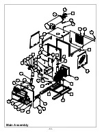
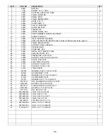
Страница 15: ...12 Main Assembly...

Страница 16: ...61 ENGINE ASM ISUZU 3CH1 1 24 20989 SUPPORT FUEL TANK 8 GALLON 2 25 20990 STRAP FUEL TANK 2 26 20994 FUEL TANK 8 GALLON 1 27 21070 EXHAUST CLAMP 2 3 8 1 28 21321 EXHUAST OUTLET VEU 1 29 21676 TUBE INS...

Страница 17: ...14 5 3 7 7 Canister and Blower Assembly...

Страница 18: ...20085 HANDLE 1 2 13 1 19 20087 ADAPTER BLOWER 1 20 20088 DOOR ROD CANISTER 1 21 20092 FITTING 3 CAMLOCK 1 22 20093 HOSE 1 4 x 18 2 23 20095 CANISTER WELDMENT 1 24 20102 FILTER CAP WELDMENT 1 25 20103...

Страница 19: ...16 Sensor Stand Assembly...

Страница 20: ...STRAIN RELIEF SMALL 1 13 20220 CORD GRIP 3 4 NPT 1 14 20222 PLUG VEU MACHINED 1 15 20867 O RING 1 50 ID X 094 for serial no 8540033 and above 1 20223 O RING 1 38 ID X 06 for serial no 8540032 and belo...

Страница 21: ...18 7 6 7 6 Control Assembly...

Страница 22: ...PVC HOSE 1 4 4 13 20402 ELECTRICAL ASM VEU 1 14 20969 BYPASS VALVE PAINTED 1 15 20970 SUPPORT CONTROL BOX PAINTED 1 16 20973 COVER CONTROL PANEL PAINTED 1 17 20974 HINGE COVER 2 18 20976 STUD 1 4 20 X...

Страница 23: ...20 5 5 1 7 5 Plug Assembly...

Страница 24: ...CONDUCTOR MALE 1 8 19477 SET SCREW 8 32 X 1 4 POINTED 1 9 20196 DOWEL PIN 25 X 1 25 1 10 20205 SOCKET VEU PLUG 1 11 20220 CORD GRIP 3 4 NPT 1 12 20589 INSULATOR DELRIN 1 13 20591 CORD BULK 18GA 2 WIRE...

Страница 25: ...22 Door Assembly...

Страница 26: ...OOR HANDLE SNAP IN 1 2 20111 EDGING DOOR 21 3 20112 LATCH DOOR 2 4 20113 PANEL DOOR 1 5 20239 DECAL VEU DOOR 1 6 7 8 9 10 11 12 13 14 15 16 17 18 19 20 21 22 23 24 25 26 27 28 29 30 31 32 33 34 35 36...

Страница 27: ...24 Engine Assembly...

Страница 28: ...19 F05SW WASHER 5 16 X 3 4 X 15GA ZP 4 20 F08LW LOCKWASHER 1 2 ZP 3 21 F0324HN NUT HEX 10 24 ZP 1 22 F0420ELN LOCKNUT 1 4 20 NYLOC 5 23 F0420FN FLANGE WHIZ LOCK NUT 1 4 20 4 24 F0518FN NUT FLANGE WHIZ...

Страница 29: ...26 Probe and Hose Assemblies...

Страница 30: ...9188 PIPE PROBE 1 5 19348 CUP VACUUM 1 6 20985 BALL VALVE 1 2 NPT 1 7 20986 PIPE BUSHING 3 8 1 2 NPT 1 8 20987 HEAD PROBE HI FLOW 1 20984 PROBE ASM HIGH FLOW INCLUDES ITEMS 1 7 19049 CAM GROOVE HOSE A...

Страница 31: ...28 9 2 7 52 1 7 5 8 5 7 5 25 7 25 1 5 5 5 7 5 1 5 5 6 16 7 2 8 62 12 67 57 5 7 51 725 2 3 8 6 7 03 5 785 8 3803 38 2 1 Y 1 0 50 5 7 5 1 6 1625 1 1 21752 2 251 1 7 21 72 Wiring Schematic...

Страница 32: ...29 NOTES...

Страница 33: ...LTS 5 This warranty does not cover the cost of transportation and other expenses which may be connected with warranty service but not specifically mentioned herein 6 This warranty does not cover any u...

Отзывы: