background image

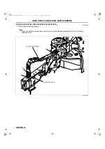
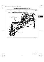
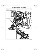
BODY STRUCTURE [PANEL REPLACEMENT]

09-80B–17

09-80B

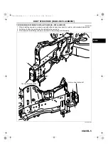
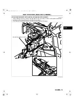
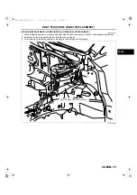
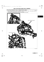
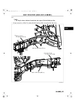
WHEEL APRON PANEL (FRONT) INSTALLATION[PANEL REPLACEMENT]

id098008741200

1. When installing new parts, measure and adjust the body as necessary to conform with standard dimensions.
2. Drill holes for the plug welding before installing the new parts.
3. After temporarily installing new parts, make sure the related parts fit properly.
4. Weld the 20 locations indicated by (A) and install the engine mount bracket.
5. Install the wheel apron panel (front).

End Of Sie

WHEEL APRON PANEL FRONT (LH)

11

12

5

5

(A)5

(A)5

(A)4

(A)6

WHEEL APRON PANEL
FRONT (RH)

ENGINE MOUNT BRACKET

acxuub00000087

3419-1U-06C(09-80B).fm  17 ページ  2006年3月24日 金曜日 午後4時47分

Содержание 2007 CX-7

Страница 1: ...the latest available at the time of printing As modifications affecting repair or maintenance occur relevant information supplementary to this volume will be made available at Mazda dealers This manu...

Страница 2: ...VEHICLE IDENTIFICATION NUMBERS VIN JM3 ER29L 7 100001 JM3 ER293 7 100001 3419 1U 06C INDEX fm 2...

Страница 3: ...OVAL OF BODY PANELS 00 00 9 Body Measurements 00 00 9 Prevention of Body Deformation 00 00 10 Selection of Cut and join Locations 00 00 10 Removal of Associated Parts 00 00 10 Rough Cutting of Damaged...

Страница 4: ...odel year Plant Serial No 0 Hiroshima 1 Hofu 7 2007 Engine Body Gross vehicle weight class 9 Wagon Gross vehicle weight class C 1814 2267 kg Carline Series ER Mazda CX 7 JM3 Mazda Multi purpose vehicl...

Страница 5: ...nd understand the notes before carrying out any procedures Example REAR FENDER PANEL REMOVAL Shows operation section Shows procedure caution and note BRAZE WELDING Shows welding region Shows a cross S...

Страница 6: ...fic indications the standard points and dimensions are symmetrical in regard to the center of the vehicle The hypothetical lines may differ according to the vehicle model The schematic diagram shows t...

Страница 7: ...acket Rear suspension housing A B C D E F G H I J K Rear side frame standard hole Rear side frame standard hole Shows bolt size Shows hole diameter Shows slot mm in UNDERBODY FLAT PLANE DIMENSIONS 16...

Страница 8: ...ons are the actual dimensions between two standard points When there are no specific indications the standard points and dimensions are symmetrical in regard to the center of the vehicle 817 FRONT FEN...

Страница 9: ...bol Designation Hole diameter or bolt or nut size mm in Point symbol Designation Hole diameter or bolt or nut size mm in Shows bolt size Shows hole diameter Shows slot 851 16 0 62 M14 0 55 31 1 22 17...

Страница 10: ...d Vehicle Protection Use seat covers and floor covers Use heat resistant protective covers to protect glass areas and seats from heat or sparks during welding Protect items such as moldings garnishes...

Страница 11: ...connect the welding machine ground near the welding area End Of Sie EFFICIENT REMOVAL OF BODY PANELS id000000600300 Body Measurements Before removal or rough cutting first measure the body at and arou...

Страница 12: ...ng associated parts Rough Cutting of Damaged Panel Verify that there are no parts such as pipes hoses and wiring harness nearby or on the opposite side of a panel which could be damaged by heat For cu...

Страница 13: ...hole in the part where the 3 4 plates are put together Also weld the plates together tightly so that gaps do not develop Application of Weld through Primer For treatment against corrosion remove the...

Страница 14: ...pe of the spot welder tip is D 2 t 3 If the upper panel thickness is different from that of the under panel adjust to the thinner one Because the weld strength is affected by the shape of the spot wel...

Страница 15: ...e the chisel between the panels according to the number of panels as shown below To determine weld strength drive the chisel between the panel and check whether the panels come apart If the panels com...

Страница 16: ...fter installation apply it before installation Application of Undercoating Apply an undercoat to the required location of the body Application of Rust Inhibitor Apply rust inhibitor wax oil etc to the...

Страница 17: ...ATION 00 00 15 00 00 ABBREVIATION id000000600700 End Of Sie CM Control module Ctr Center DSC Dynamic stability control Fr Front HU Hydraulic unit LH Left M Metallic MC Mica RH Right Rr Rear 3419 1U 06...

Страница 18: ......

Страница 19: ...80C BODY STRUCTURE DIMENSIONS 09 80D BODY STRUCTURE PLASTIC BODY PARTS 09 80E Toc of SCT 09 80A BODY STRUCTURE CONSTRUCTION BODY COMPONENTS CONSTRUCTION CONSTRUCTION 09 80A 2 ULTRA HIGH TENSION STEEL...

Страница 20: ...TS CONSTRUCTION CONSTRUCTION id098007739700 1 3 2 5 4 9 8 7 10 6 13 11 12 14 15 16 19 18 17 20 28 27 26 24 25 23 22 21 29 30 37 36 34 33 32 31 38 39 43 45 41 47 50 49 48 51 57 56 55 52 54 58 59 42 46...

Страница 21: ...mber x 1 20 0 047 18 Dash lower panel x 0 80 0 031 19 Cowl panel x 0 70 0 028 20 Wiper bracket x 1 60 0 063 21 Hinge pillar inner x x 1 00 0 039 22 Hinge pillar reinforcement x 1 60 0 063 23 Side sill...

Страница 22: ...0 65 0 026 51 Front B frame x x 2 30 0 090 52 Tunnel reinforcement x x 1 40 0 055 53 Crossmember No 3 x x 1 40 0 055 54 Trunk floor pan x 0 65 0 026 55 Crossmember No 4 x x 1 20 0 047 56 Rear side fr...

Страница 23: ...use the ultra high tensile steel is hard and it may be difficult to reform when extracting the damaged part using a frame repair machine perform the work verifying that other parts are not affected Wh...

Страница 24: ...REAR 1 FRONT SIDE FRAME OUTER FRONT 1 FRONT SIDE FRAME OUTER CENTER 1 1 1 REAR FRAME REINFORCEMENT FIXING REINFORCEMENT REAR FRAME REINFORCEMENT FRONT 1 REAR FRAME GUSSET 1 REAR SIDE FRAME FRONT 3 CR...

Страница 25: ...MPONENT INSTALLATION PANEL REPLACEMENT 09 80B 22 FRONT SIDE FRAME PARTIAL CUTTING REMOVAL PANEL REPLACEMENT 09 80B 24 RH 09 80B 24 LH 09 80B 25 FRONT SIDE FRAME PARTIAL CUTTING INSTALLATION PANEL REPL...

Страница 26: ...RUCTURE PANEL REPLACEMENT 09 80B 2 FRONT BUMPER BRACKET REMOVAL PANEL REPLACEMENT id098008743100 1 Remove the front bumper bracket End Of Sie FRONT BUMPER BRACKET BOLT acxuub00000072 3419 1U 06C 09 80...

Страница 27: ...alling new parts measure and adjust the body as necessary to conform with standard dimensions 2 Tighten the bolts at section A to the specified torque and install the front bumper bracket Tightening t...

Страница 28: ...REPLACEMENT 09 80B 4 TIEDOWN REINFORCEMENT REMOVAL PANEL REPLACEMENT id098008800200 1 Remove the tiedown reinforcement End Of Sie 3 1 TIEDOWN REINFORCEMENT 3 1 TIEDOWN REINFORCEMENT acxuub00000074 341...

Страница 29: ...measure and adjust the body as necessary to conform with standard dimensions 2 Drill holes for the plug welding before installing the new parts 3 After temporarily installing new parts make sure the...

Страница 30: ...EL REPLACEMENT id098008800400 1 Remove the shroud upper panel Note When removing the shroud upper panel and the shroud side panel separately drill the 3 locations indicated by A End Of Sie SHROUD UPPE...

Страница 31: ...asure and adjust the body as necessary to conform with standard dimensions 2 Drill holes for the plug welding before installing the new parts 3 After temporarily installing new parts make sure the rel...

Страница 32: ...PANEL REPLACEMENT 09 80B 8 COWL SIDE REINFORCEMENT REMOVAL PANEL REPLACEMENT id098008741700 1 Remove the cowl side reinforcement End Of Sie 5 1 5 6 6 COWL SIDE REINFORCEMENT acxuub00000078 3419 1U 06...

Страница 33: ...new parts measure and adjust the body as necessary to conform with standard dimensions 2 Drill holes for the plug welding before installing the new parts 3 After temporarily installing new parts make...

Страница 34: ...STRUCTURE PANEL REPLACEMENT 09 80B 10 WIPER BRACKET COMPONENT REMOVAL PANEL REPLACEMENT id098008750000 1 Remove the wiper bracket End Of Sie WIPER BRACKET 2 2 3 4 acxuub00000080 3419 1U 06C 09 80B fm...

Страница 35: ...ng new parts measure and adjust the body as necessary to conform with standard dimensions 2 Drill holes for the plug welding before installing the new parts 3 After temporarily installing new parts ma...

Страница 36: ...ER REMOVAL PANEL REPLACEMENT id098008800000 1 Drill the 1 location indicated by A from the bottom as they cannot be seen from the outer side 2 Remove the apron reinforcement upper End Of Sie APRON REI...

Страница 37: ...nstalling new parts measure and adjust the body as necessary to conform with standard dimensions 2 Drill holes for the plug welding before installing the new parts 3 After temporarily installing new p...

Страница 38: ...EL REPLACEMENT 09 80B 14 APRON REINFORCEMENT LOWER REMOVAL PANEL REPLACEMENT id098008741300 1 Remove the apron reinforcement lower End Of Sie 5 3 4 5 2 APRON REINFORCEMENT LOWER acxuub00000084 3419 1U...

Страница 39: ...w parts measure and adjust the body as necessary to conform with standard dimensions 2 Drill holes for the plug welding before installing the new parts 3 After temporarily installing new parts make su...

Страница 40: ...NT 09 80B 16 WHEEL APRON PANEL FRONT REMOVAL PANEL REPLACEMENT id098008741100 1 Remove the wheel apron panel front End Of Sie 5 11 12 5 WHEEL APRON PANEL FRONT LH WHEEL APRON PANEL FRONT RH acxuub0000...

Страница 41: ...ions 2 Drill holes for the plug welding before installing the new parts 3 After temporarily installing new parts make sure the related parts fit properly 4 Weld the 20 locations indicated by A and ins...

Страница 42: ...ENT 09 80B 18 WHEEL APRON COMPONENT REMOVAL PANEL REPLACEMENT id098008746000 1 Remove the wheel apron component End Of Sie 2 RH 22 LH 21 3 2 4 4 WHEEL APRON COMPONENT WHEEL APRON COMPONENT acxuub00000...

Страница 43: ...and adjust the body as necessary to conform with standard dimensions 2 Drill holes for the plug welding before installing the new parts 3 After temporarily installing new parts make sure the related p...

Страница 44: ...80B 20 FRONT SIDE FRAME COMPONENT REMOVAL PANEL REPLACEMENT id098008741900 1 Rough cut area A drill the 14 locations indicated by B FRONT SIDE FRAME COMPONENT A ROUGH CUT LOCATION B 5 B 3 A A A A acxu...

Страница 45: ...0B 2 Drill the 2 locations indicated by C and remove the front side frame component Note The 2 weld locations indicated by C cannot be seen from the interior End Of Sie B 2 B 4 FRONT SIDE FRAME COMPON...

Страница 46: ...parts measure and adjust the body as necessary to conform with standard dimensions 2 Drill holes for the plug welding before installing the new parts 3 To prepare for installation drill 2 through hole...

Страница 47: ...B 5 After temporarily installing new parts make sure the related parts fit properly 6 Weld the remaining weld locations and install the front side frame component End Of Sie 2 4 FRONT SIDE FRAME COMPO...

Страница 48: ...tes the maximum size range of the installation position 1 Rough cut area A drill the 18 locations indicated by B and then remove the front side frame B 7 B 8 B 3 30mm FRONT SIDE FRAME OUTER RH 1 18in...

Страница 49: ...lation position 1 Rough cut area A drill the 18 locations indicated by B and then remove the front side frame End Of Sie B 7 B 8 B 3 FRONT SIDE FRAME OUTER LH 50mm A ROUGH CUT AND CUT AND JOIN LOCATIO...

Страница 50: ...ew and existing parts 3 Drill holes for the plug welding before installing the new parts 4 When installing the new parts trial fit new and existing parts and then measure and adjust the body to confor...

Страница 51: ...0B FRONT SIDE FRAME INNER RH 85mm L 70mm x 2 L 30mm x 2 EXTRUSION BEAD EXTRUSION BEAD 100mm 25mm t 2 3mm REINFORCEMENT CUT AND JOIN LOCATION 1 18in 0 98in 0 09in 3 94in 2 76in 3 35in 15mm 0 59in 10mm...

Страница 52: ...de frame reinforcement 8 Install the suspension mount reinforcement 9 Install the suspension mount bolt Tightening torque 1 0 5 0 N m 11 50 kgf cm 8 9 44 in lbf L 50mm 2 1 97in L 50mm 1 97in FRONT SID...

Страница 53: ...BODY STRUCTURE PANEL REPLACEMENT 09 80B 29 09 80B 4 L 20mm 2 SUSPENSION MOUNT REINFORCEMENT SUSPENSION MOUNT BOLT L 15mm 0 59in 0 79in am8rrb00000041 3419 1U 06C 09 80B fm 29...

Страница 54: ...arts by plug welding from the outside then butt weld the new and existing parts Caution Press fit the reinforcement panel and the body side material and then plug weld them 11 After temporarily instal...

Страница 55: ...for the plug welding before installing the new parts 4 When installing the new parts trial fit new and existing parts and then measure and adjust the body to conform with standard dimensions 5 Trial f...

Страница 56: ...05mm FRONT SIDE FRAME INNER LH 100mm 25mm REINFORCEMENT CUT AND JOIN LOCATION 4 13in 0 09in 0 98in 3 94in L 70mm x 2 L 30mm x 2 t 2 3mm 1 18in 2 76in EXTRUSION BEAD EXTRUSION BEAD 15mm 0 59in 10mm 0 3...

Страница 57: ...t side frame reinforcement 8 Install the suspension mount reinforcement 9 Install the suspension mount bolt Tightening torque 1 0 5 0 N m 11 50 kgf cm 8 9 44 in lbf L 50mm 1 97in L 50mm 2 1 97in FRONT...

Страница 58: ...BODY STRUCTURE PANEL REPLACEMENT 09 80B 34 4 2 SUSPENSION MOUNT REINFORCEMENT SUSPENSION MOUNT BOLT L 20mm L 15mm 0 59in 0 79in am8rrb00000044 3419 1U 06C 09 80B fm 34...

Страница 59: ...lug welding from the outside then butt weld the new and existing parts Caution Press fit the reinforcement panel and the body side material and then plug weld them 11 After temporarily installing new...

Страница 60: ...en removing the torque box the nut plate may interfere and make removal difficult Therefore drill the 3 locations indicated by A and then open the nut plate outward 2 Drill the 25 locations indicated...

Страница 61: ...TURE PANEL REPLACEMENT 09 80B 37 09 80B 3 Rough cut area C drill the 2 locations indicated by D then remove the torque box End Of Sie D 2 ROUGH CUT LOCATION TORQUE BOX C acxuub00000146 3419 1U 06C 09...

Страница 62: ...g new parts measure and adjust the body as necessary to conform with standard dimensions 2 Drill holes for the plug welding before installing the new parts 3 After temporarily installing new parts mak...

Страница 63: ...BODY STRUCTURE PANEL REPLACEMENT 09 80B 39 09 80B End Of Sie BM FRONT FRAME REAR L 90mm 3 54in TORQUE BOX acxuub00000148 3419 1U 06C 09 80B fm 39...

Страница 64: ...80B 40 FRONT FRAME REAR REMOVAL PANEL REPLACEMENT id098008742500 1 Remove the front frame rear component End Of Sie FRONT FRAME REAR COMPONENT FRONT FRAME REAR COMPONENT 9 10 13 7 17 4 3 2 3 3 5 acxu...

Страница 65: ...ust the body as necessary to conform with standard dimensions 2 Drill holes for the plug welding before installing the new parts 3 After temporarily installing new parts make sure the related parts fi...

Страница 66: ...1 Rough cut area A drill the 78 locations indicated by B 2 Drill the 1 locations indicated by C from the interior 3 Remove the front pillar outer C 1 B 11 A B 3 B 18 CUT AND JOIN LOCATION FRONT PILLAR...

Страница 67: ...Y STRUCTURE PANEL REPLACEMENT 09 80B 43 09 80B B 7 B 2 B 2 A B 25 B 10 CUT AND JOIN LOCATION FRONT PILLAR OUTER ROUGH CUT LOCATION 40mm 1 57in 40mm 1 57in B B B B acxuub00000097 3419 1U 06C 09 80B fm...

Страница 68: ...ated by E from the interior 6 Remove the front pillar reinforcement E 2 FRONT PILLAR REINFORCEMENT CUT AND JOIN LOCATION ROUGH CUT LOCATION 30mm 1 18in 125mm 4 92in 110mm 4 33in 40mm 1 57in D A A A A...

Страница 69: ...ill the 3 locations indicated by G and then remove the front pillar inner 8 Remove the spot weld sealer using a disc grinder End Of Sie G 2 F G 1 FRONT PILLAR INNER CUT AND JOIN LOCATION ROUGH CUT LOC...

Страница 70: ...location shown in the figure and chamfer the joint surfaces of the new and existing parts 2 Drill holes for the plug welding before installing the new parts 3 Apply body sealer to the joints of old an...

Страница 71: ...dicated by A on the existing parts Install the reinforcement and the existing parts by plug welding from the outside then butt weld the new and existing parts Caution Press fit the reinforcement panel...

Страница 72: ...ons indicated by C on the existing parts Install the reinforcement and the existing parts by plug welding from the outside then butt weld the new and existing parts Caution Press fit the reinforcement...

Страница 73: ...rts make sure the related parts fit properly 12 Drill the 1 locations indicated by D from the interior 13 Weld the 81 locations indicated by E and install the front pillar outer D 1 E 12 E 3 E 18 CUT...

Страница 74: ...BODY STRUCTURE PANEL REPLACEMENT 09 80B 50 End Of Sie BM CENTER PILLAR E 8 E 2 E 2 E 26 E 10 CUT AND JOIN LOCATION FRONT PILLAR OUTER 40mm 1 57in acxuub00000103 3419 1U 06C 09 80B fm 50...

Страница 75: ...ed by B then remove the center pillar outer B 14 B 19 A B 2 B 1 B 21 CENTER PILLAR OUTER 40mm 1 57in 20mm 0 79in 120mm 4 72in 20mm 0 79in 30mm 1 18in 130mm 5 12in CUT AND JOIN LOCATION CUT AND JOIN LO...

Страница 76: ...Drill the 3 locations indicated by E from the interior 4 Remove the center pillar inner reinforcement CENTER PILLAR REINFORCEMENT 110mm 4 33in 150mm 5 90in 20mm 0 79in 30mm 180mm 1 18in 7 09in ROUGH...

Страница 77: ...09 80B 5 Rough cut area F drill the 2 locations indicated by G then remove the center pillar inner End Of Sie CENTER PILLAR INNER 190mm 7 48in 1 18in 30mm G 2 CUT AND JOIN LOCATION ROUGH CUT LOCATION...

Страница 78: ...e body side material and then weld them 5 Install the center pillar inner 6 Make a reinforcement panel using the material from the center pillar reinforcement 7 Because the center pillar reinforcement...

Страница 79: ...ily installing new parts make sure the related parts fit properly CENTER PILLAR REINFORCEMENT 110mm 4 33in 150mm 5 90in 180mm 7 09in ROUGH CUT AND CUT AND JOIN LOCATION CUT AND JOIN LOCATION CUT AND J...

Страница 80: ...11 Install the center pillar outer End Of Sie BM SIDE SILL PANEL 15 21 2 1 22 CENTER PILLAR OUTER 40mm 1 57in 120mm 4 72in 130mm 5 12in CUT AND JOIN LOCATION CUT AND JOIN LOCATION CUT AND JOIN LOCATI...

Страница 81: ...locations indicated by B and then remove the side sill outer B 1 CUT AND JOIN LOCATION CUT AND JOIN LOCATION ROUGH CUT LOCATION A ROUGH CUT LOCATION A SIDE SILL OUTER B 1 B 3 B 13 B 5 B 20 B 36 B 23...

Страница 82: ...orcement inner indicated by dotted lines in the figure 3 Drill the 5 locations indicated by D from the interior 4 Remove the side sill reinforcement End Of Sie CUT AND JOIN LOCATION ROUGH CUT LOCATION...

Страница 83: ...the inside of the panel drill 3 plug weld holes at the locations indicated by A on the existing parts Install the reinforcement and the existing parts by plug welding from the outside then butt weld...

Страница 84: ...make sure the related parts fit properly 8 Install the side sill outer End Of Sie BM REAR FENDER PANEL CUT AND JOIN LOCATION CUT AND JOIN LOCATION SIDE SILL OUTER 1 4 14 6 21 36 24 140mm 100mm 80mm C...

Страница 85: ...the tire arch line Use a chisel or similar tool to separate the rear fender panel from the rear pillar inner then remove the rear fender panel 3 Remove the rear fender panel 4 Remove the spot weld sea...

Страница 86: ...BODY STRUCTURE PANEL REPLACEMENT 09 80B 62 B 7 B 1 B 3 B 6 B 10 REAR FENDER PANEL acxuub00000116 3419 1U 06C 09 80B fm 62...

Страница 87: ...BODY STRUCTURE PANEL REPLACEMENT 09 80B 63 09 80B 5 Remove the rear fender panel lower End Of Sie 6 8 1 1 REAR FENDER LOWER acxuub00000117 3419 1U 06C 09 80B fm 63...

Страница 88: ...ssary to conform with standard dimensions 2 Drill holes for the plug welding before installing the new parts 3 Install the rear fender panel lower 4 Before installing new parts apply spot weld sealer...

Страница 89: ...BODY STRUCTURE PANEL REPLACEMENT 09 80B 65 09 80B 6 Install the rear fender panel 7 1 3 6 10 REAR FENDER PANEL acxuub00000119 3419 1U 06C 09 80B fm 65...

Страница 90: ...EPLACEMENT 09 80B 66 End Of Sie BM REAR END PANEL 6 1 45mm 1 77in 180mm 7 09in 30mm 1 18in REAR FENDER PANEL 8 12 23 CUT AND JOIN LOCATION CUT AND JOIN LOCATION CUT AND JOIN LOCATION acxuub00000120 34...

Страница 91: ...MOVAL PANEL REPLACEMENT id098008744500 1 Drill the 2 locations indicated by A from the interior 2 Remove the rear end panel 3 Remove the spot weld sealer using a disc grinder End Of Sie 6 6 26 5 5 2 2...

Страница 92: ...with standard dimensions 2 Drill holes for the plug welding before installing the new parts 3 Apply spot weld sealer to the joints of old and new parts for waterproofing and rust protection 4 After t...

Страница 93: ...1 Rough cut area A drill the 9 locations indicated by B Note When removing the rear pillar outer and corner plate separately drill the 5 locations indicated by C CUT AND JOIN LOCATION ROUGH CUT LOCATI...

Страница 94: ...REPLACEMENT 09 80B 70 2 Rough cut area D drill the 13 locations indicated by E CUT AND JOIN LOCATION ROUGH CUT LOCATION REAR PILLAR REINFORCEMENT E 7 D E 6 9 84in 250mm 30mm 1 18in acxuub00000124 3419...

Страница 95: ...BODY STRUCTURE PANEL REPLACEMENT 09 80B 71 09 80B 3 Remove the corner junction End Of Sie CORNER JUNCTION 2 6 5 acxuub00000125 3419 1U 06C 09 80B fm 71...

Страница 96: ...joining and cutting the new and existing parts trial fit the new part in position then measure and adjust the body as necessary to conform with standard dimensions 2 Drill holes for plug welds before...

Страница 97: ...BODY STRUCTURE PANEL REPLACEMENT 09 80B 73 09 80B 4 Install the rear pillar reinforcement CUT AND JOIN LOCATION REAR PILLAR REINFORCEMENT 9 6 9 84in 250mm acxuub00000127 3419 1U 06C 09 80B fm 73...

Страница 98: ...ed parts fit properly 6 Install the rear pillar outer Note When replacing the rear pillar outer and corner plate separately weld the 5 locations indicated by A End Of Sie BM TRUNK FLOOR PAN CUT AND JO...

Страница 99: ...ODY STRUCTURE PANEL REPLACEMENT 09 80B 75 09 80B REAR FLOOR PAN REMOVAL PANEL REPLACEMENT id098008742700 1 Remove the crossmember No 5 9 18 18 9 CROSSMEMBER No 5 acxuub00000139 3419 1U 06C 09 80B fm 7...

Страница 100: ...ing be careful not to damage the crossmember No 4 indicated by dotted lines in the figure 3 Drill the remaining locations then remove the rear floor pan REAR FLOOR PAN 13 10 A 40mm 1 57in 60mm 2 36in...

Страница 101: ...BODY STRUCTURE PANEL REPLACEMENT 09 80B 77 09 80B End Of Sie 4 8 REAR FLOOR PAN acxuub00000141 3419 1U 06C 09 80B fm 77...

Страница 102: ...alling the new parts 4 Apply spot sealer to the areas where both the overlapping ends of the new and existing parts will be welded Adhere the sections to be welded and fillet weld along both seams at...

Страница 103: ...BODY STRUCTURE PANEL REPLACEMENT 09 80B 79 09 80B 4 8 REAR FLOOR PAN acxuub00000143 3419 1U 06C 09 80B fm 79...

Страница 104: ...CEMENT 09 80B 80 6 After temporarily installing new parts make sure the related parts fit properly 7 Install the crossmember No 5 End Of Sie BM REAR SIDE FRAME 9 18 18 9 CROSSMEMBER No 5 acxuub0000014...

Страница 105: ...80B REAR SIDE FRAME REMOVAL PANEL REPLACEMENT id098008801200 1 Rough cut and remove the damaged part of the rear side frame End Of Sie 145mm 5 71in CUT AND JOIN LOCATION ROUGH CUT LOCATION REAR SIDE...

Страница 106: ...new and existing parts then measure and adjust the body to conform with standard dimensions 4 After temporarily installing new parts make sure the related parts fit properly 5 Trial fit the new and ex...

Страница 107: ...RUCTURE PANEL REPLACEMENT 09 80B 83 09 80B BM ROOF PANEL ROOF PANEL REMOVAL PANEL REPLACEMENT id098008744300 1 Remove the roof panel End Of Sie ROOF PANEL 19 22 22 25 acxuub00000135 3419 1U 06C 09 80B...

Страница 108: ...ing new parts measure and adjust the body as necessary to conform with standard dimensions 2 Drill holes for the plug welding before installing the new parts 3 After temporarily installing new parts m...

Страница 109: ...OF AND RUST PREVENTIVE 09 80C 2 UNDER COATING WATER PROOF AND RUST PREVENTIVE 09 80C 5 CHIPPING RESISTANT COATING WATER PROOF AND RUST PREVENTIVE 09 80C 5 RUST PREVENTIVE TREATMENT WATER PROOF AND RUS...

Страница 110: ...NG WATER PROOF AND RUST PREVENTIVE id098009739800 Sealant is applied to the parts where the panels meet and to the hemmed parts of the door panel and hood panel to provide water proofing and rust proo...

Страница 111: ...BODY STRUCTURE WATER PROOF AND RUST PREVENTIVE 09 80C 3 09 80C acxuub00000019 3419 1U 06C 09 80C fm 3...

Страница 112: ...BODY STRUCTURE WATER PROOF AND RUST PREVENTIVE 09 80C 4 End Of Sie acxuub00000020 3419 1U 06C 09 80C fm 4...

Страница 113: ...COATING WATER PROOF AND RUST PREVENTIVE id098009739900 The shaded areas indicated under body locations that are undercoated to prevent noise and rusting End Of Sie CHIPPING RESISTANT COATING WATER PR...

Страница 114: ...BODY STRUCTURE WATER PROOF AND RUST PREVENTIVE 09 80C 6 2007 Mazda CX 7 Bodyshop Manual 3419 1U 06C RUST PREVENTIVE TREATMENT WATER PROOF AND RUST PREVENTIVE id098009740100 End Of Sie acxuub00000023...

Страница 115: ...NTIVE 09 80C 7 09 80C DUMPING SHEET REPLACEMENT WATER PROOF AND RUST PREVENTIVE id098009745700 After repairing the body attach the dumping sheet to the location shown in the figure for noise insulatio...

Страница 116: ......

Страница 117: ...RONT BODY STRAIGHT LINE DIMENSIONS 2 DIMENSIONS 09 80D 5 FRONT BODY STRAIGHT LINE DIMENSIONS 3 DIMENSIONS 09 80D 6 CABIN SIDE FRAME STRAIGHT LINE DIMENSIONS DIMENSIONS 09 80D 7 ROOM STRAIGHT LINE DIME...

Страница 118: ...24 84 11 65 2 20 14 13 17 32 23 86 15 31 20 31 0 55 25 00 acxuub00000001 Point symbol Designation Hole diameter or bolt or nut size mm in A Front side frame datum hole 14 0 55 B Front suspension moun...

Страница 119: ...87 LH RH acxuub00000002 Fr Fr Fr Fr Fr Fr Fr Fr Fr A B C B A E D D E F G H I J L acxuub00000003 Point symbol Designation Hole diameter or bolt or nut size mm in A Front side frame datum hole 14 0 55 B...

Страница 120: ...48 39 37 68 36 22 33 66 acxuub00000004 Fr Fr Fr Fr Fr A B C D E acxuub00000005 Point symbol Designation Hole diameter or bolt or nut size mm in A Roof seamless location B Front pillar projection loca...

Страница 121: ...8 35 41 10 23 98 in 39 92 10 04 9 25 acxuub00000006 Fr Fr Fr Fr Fr A B C D E acxuub00000007 Point symbol Designation Hole diameter or bolt or nut size mm in A Hood hinge installation hole 14 0 55 B Su...

Страница 122: ...7 99 43 62 35 75 59 06 15 16 25 28 9 53 54 33 in acxuub00000008 A B F C D E Fr Fr Fr Fr Fr Fr acxuub00000009 Point symbol Designation Hole diameter or bolt or nut size mm in A Dash member upper datum...

Страница 123: ...mm in A B C D E F G H I K J 1 194 1 125 1 136 1 711 1 031 917 1 552 1 189 1 105 1 067 1 156 396 711 580 607 15 59 27 99 22 83 23 90 47 01 44 29 44 72 67 36 40 59 36 10 61 10 46 81 43 25 42 01 45 51 mm...

Страница 124: ...Side frame outer notch Point symbol Designation Hole diameter or bolt or nut size mm in I Side frame outer datum hole 8 2 0 32 J Side frame outer datum hole 4 5 0 18 K Front side frame outer datum slo...

Страница 125: ...inner datum hole 7 0 28 C Front pillar inner reinforcement datum hole 10 0 39 D Hinge pillar inner datum hole 8 6 0 34 E Instrument panel bracket datum slot 12 18 0 47 0 71 F Center pillar inner datum...

Страница 126: ...Point symbol Designation Hole diameter or bolt or nut size mm in A Center pillar inner datum hole 16 0 63 B Center pillar inner datum hole 10 0 39 C Center pillar inner square hole 26 6 1 02 0 24 D D...

Страница 127: ...nt symbol Designation Hole diameter or bolt or nut size mm in A Rear pillar inner datum hole 7 0 28 B Rear seat bracket datum hole 5 0 20 C Rear pillar inner datum hole 7 0 28 D Crossmember No 5 datum...

Страница 128: ...18 15 38 54 23 62 48 90 11 97 56 34 acxuub00000016 Fr Fr Fr Fr Fr Fr Fr A B C D E F F acxuub00000017 Point symbol Designation Hole diameter or bolt or nut size mm in A Liftgate hinge installation hole...

Страница 129: ...nd Of Sie F Rear end panel datum hole 12 0 47 Point symbol Designation Hole diameter or bolt or nut size mm in F Rear end panel datum slot 12 18 0 47 0 71 Point symbol Designation Hole diameter or bol...

Страница 130: ......

Страница 131: ...L GRILLE PP POLYPROPYLENE 95 203 FRONT COMBINATION LIGHT LENS PC POLYCARBONATE 130 266 HOUSING PP POLYPROPYLENE 90 194 RADIATOR GRILLE PP POLYPROPYLENE 95 203 FRONT BUMPER PP POLYPROPYLENE 100 212 OUT...

Страница 132: ...ew one because such repair would detract from the looks and quality of the bumper In addition such repair is not considered reasonable in terms of work time Repairable Bumpers 1 A bumper with a hole l...

Страница 133: ...rea Rough sand damage area Degrease damaged area Apply repair agent to damaged area and let dry Sand damaged area smooth Sand dam aged area Apply polypropylene primer to damaged area and let dry Spray...

Страница 134: ...the damage with a knife to make it smooth Sand the area with a sander to make an angle of about 45 Hole A A A A Section Crack B B C C Flaw D D B B C C Section D D Section Top coat layer Primer layer P...

Страница 135: ...If the part is welded with the welding rod melted like jelly the welding strength will be reduced Hold the heat gun 10 20 mm 0 39 0 79 in from the part being welded Do not move the welding rod until...

Страница 136: ...rm The repair agent hardens quickly about 5 minutes proceed with the work immediately after mixing the agents Allow about 30 minutes to dry 20 C 68 F before sanding The repair agent is a two part epox...

Страница 137: ...inted surface 9 Mix the primer and the hardener at a ratio of one to one Apply the primer to the repaired area and the surface of the bumper with a brush or spray Use the primer within 16 hours after...

Страница 138: ...e surface of the bumper with 400 600 sandpaper Do not expose the surface of the polypropylene Wet or dry sanding is acceptable 14 Wipe the complete surface of the bumper with degreasing agent Quickly...

Отзывы: