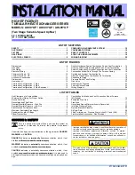
background image

30

Alternate

Gas Line

Location

Gas Valve

Burners

Manual Shut Off Valve

(upstream from

ground joint

         pipe union)

Drip Leg

Grommet

in Standard

Gas Line

Hole

*Ground

Joint

Pipe

Union

*Ground

Joint

Pipe

Union

*NOTE: Union may be inside furnace cabinet where allowed by local codes.

Manifold

UPFLOW

Figure 32

Alternate

Gas Line

Location

Plug in

Alternate

Gas Line

Hole

Gas Valve

Burners

Manual Shut Off Valve

(upstream from ground joint pipe union)

Drip Leg

Grommet

in Standard

Gas Line

Hole

*Ground

Joint

Pipe Union

*Ground

Joint

Pipe Union

*NOTE: Union may be inside furnace cabinet where allowed by local codes.

COUNTERFLOW

Figure 33

Drip Leg

Plug in Main Gas Line Hole

Alternate

Union

Location

Manual Shut Off Valve

          (upstream from

            ground joint pipe union)

Gas

Valve

Burners

Drain Trap

Manifold

Plug in Alternate Gas Line Hole

Grommet in

Standard Gas Line Hole

UPFLOW - HORIZONTAL LEFT

Figure 34

Manual Shut Off Valve

          (upstream from

            ground joint

            pipe union)

COUNTERFLOW - HORIZONTAL RIGHT

Figure 35

Gas Piping Checks

Before placing unit in operation, leak test the unit and gas 

connections.

Содержание Amana CES9 Series

Страница 1: ...trademark of Maytag Corporation or its related companies and is used under license All rights reserved IOG 2020D 04 2020 ONLY PERSONNEL THAT HAVE BEEN TRAINED TO INSTALL ADJUST SERVICE OR REPAIR HERE...

Страница 2: ...ss 25 115 Volt Line Connections 25 Junction Box Relocation 25 24 Volt Thermostat Wiring 26 Single Stage Heating Thermostat Application 26 24 Volt Dehumidistat Wiring 27 Fossil Fuel Applications 27 115...

Страница 3: ...and operation thoroughly read this manual for specifics pertaining to the installation and application of this product This furnace is manufactured for use with natural gas It may be field converted t...

Страница 4: ...alement pour la d tection de fuites Un incendie ou une explosion risque de se produire ce qui peut entra ner la mort des blessures ou des dommages mat riels Advertencia especial para la instalaci n de...

Страница 5: ...rnaces 1 Disconnect all power to the furnace Do not touch the integrated control module or any wire connected to the control prior to discharging your body s electrostatic charge to ground 2 Firmly to...

Страница 6: ...gas fitter A T handle gas cock must be used If the unit is to be installed in an attic the passageway to and the service area around the unit must have flooring To ensure proper furnace operation ins...

Страница 7: ...nt furnace from airborne contaminants To ensure that the enclosed non direct vent furnace has an adequate supply of combustion air vent from a nearby uncontaminated room or from outdoors Refer to the...

Страница 8: ...in front of the unit A furnace installed in a confined space i e a closet or utility room must have two ventilation openings with a total minimum free area of 0 25 square inches per 1 000 BTU hr of f...

Страница 9: ...moment de sa mise en marche cela peut entra ner une intoxication au monoxyde de carbone ou la mort Les tapes suivantes doivent tre suivies pour chacun des appareils raccord s au syst me de ventilation...

Страница 10: ...he furnace is installed in a crawl space it must be sus pended from the floor joist or supported by a concrete pad Never install the furnace on the ground or allow it to be exposed to water Front Cove...

Страница 11: ...25mm 10 0 w c 6 0 w c None Gas Altitude Kit Orifice Manifold Pressure Pressure Switch Change 0 7000 1 LPM 07 supports both Honeywell and White Rodgers 1 stage valves NOTE In Canada gas furnaces are on...

Страница 12: ...THE FLUE SYSTEM CAN RESULT IN SERIOUS PERSONAL INJURY OR DEATH DUE TO EXPOSURE TO FLUE PRODUCTS INCLUDING CARBON MONOXIDE WARNING FAILURE TO FOLLOW THESE INSTRUCTIONS CAN RESULT IN BODILY INJURY OR DE...

Страница 13: ...t from the fur nace Horizontal runs of vent flue piping must be supported every three to five feet and must maintain a 1 4 inch per foot downward slope back towards the furnace to properly return cond...

Страница 14: ...used must be of the same manufacturer as the vent system For Royal Pipe System 636 use GVS 65 Primer Purple and GVS 65 PVC Solvent Cement For IPEX System 636 use PVC CPVC Primer Purple or clear Use PV...

Страница 15: ...take pipe coupling Combustion Air Exhaust Tee Installation in Intake Pipe Figure 8B VENT DRAIN Figure 8C COMBUSTION AIR INTAKE OPTIONS The RF000142 coupling Figure 8B can be secured directly to the fu...

Страница 16: ...binet plug in unused combustion air hole 3 Drill a pilot hole at the cabinet dimple size dictated by knockout tool used 4 Use a knockout tool to create a 3 diameter hole 5 Install combustion air flang...

Страница 17: ...ent pipe can be run horizontally with an exit through the side of the building or run vertically with an exit through the roof of the building The vent can also be run through an existing unused chimn...

Страница 18: ...ion air intake and a vent flue pipe The pipes may be run horizontally and exit through the side of the building or run vertically and exit through the roof of the building The pipes may be run through...

Страница 19: ...ly as through a roof or horizontally as through an outside wall Vertical pipe terminations should be as shown in the follow ing figure Refer to Vent Flue Pipe and Combustion Pipe Termination Location...

Страница 20: ...urnace and drain location must maintain a 1 4 inch per foot downward slope toward the drain Do not trap the drain line in any other location than at the drain trap supplied with the furnace If the dra...

Страница 21: ...ter Drain Exiting Right Side 1 Locate and Install the 45 pipe hose drain coupling from the outside of the cabinet barbed end goes in the cabinet through hole in the right side of the cabinet and secur...

Страница 22: ...he large set of holes in the top mounting tabs of the trap into the two pre drilled holes in the side of the cabinet 9 Refer to Field Supplied Drain section for instructions on field supplied installe...

Страница 23: ...nd of tube 5 through the lower cabinet drain hole 6 Insert 100 degree elbow in the cut end of hose 5 7 Locate hose 6 Using red clamps connect between the coupling and 100 degree elbow cutting off exce...

Страница 24: ...HOCK WIRING TO THE UNIT MUST BE POLARIZED AND GROUNDED WARNING Counterflow Model Installed Horizontally with Right Side Down See Figure 28 Minimum 5 1 2 clearance is required for the drain trap beneat...

Страница 25: ...or coded for identification purposes Refer to the wiring diagram for wire routings If any of the original wire as sup plied with the furnace must be replaced it must be replaced with wiring material h...

Страница 26: ...cessary for the installer to supply additional line voltage wiring to the inside of the furnace the wiring must conform to all local codes and have a minimum tempera ture rating of 105 C All line volt...

Страница 27: ...e maintained to prevent unreliable ignition The maximum must 3 Relocate junction box and associated plugs and grommets to opposite side panel Secure with screws removed in step WIRE ROUTING MUST NOT I...

Страница 28: ...ion kit Taps for measuring the gas supply pressure and manifold pressure are provided on the valve The gas valve has a manual ON OFF control located on the valve itself This control may be set only to...

Страница 29: ...176 C28 CR 33 R95 R171 Q13 R1 38 Q 1 C3 5 C3 4 C3 2 C4 3 C42 K4 C41 K3 K1 C40 C3 0 R11 6 R10 C1 7 2 CR5 D H U M CR2 Y1 Y Y2 R59R16R87R78 CR8 CR 39 FLAME CURRENT 1VDC 1UA CR38 R25 R24 R2 6 R37 R36 R3 8...

Страница 30: ...n Drip Leg Grommet in Standard Gas Line Hole Ground Joint Pipe Union Ground Joint Pipe Union NOTE Union may be inside furnace cabinet where allowed by local codes COUNTERFLOW Figure 33 Drip Leg Plug i...

Страница 31: ...hree main factors 1 Vaporization rate depending on temperature of the liquid and wetted surface area of the con tainer or containers 2 Proper pressure regulation Two stage regulation is recommended fo...

Страница 32: ...heses components as shown in the following drawing 4 Consult proper tables for the quantity of air If the total external static pressure exceeds the maximum listed on the furnace rating plate check fo...

Страница 33: ...14 x 25 Bottom MES9 0603BN 1 16 X 25 Side or Bottom MES9 0803BN 1 16 X 25 Side or Bottom MES9 0804CN 1 16 X 25 Side or Bottom MES9 0805CN 1 20 X 25 Bottom 2 16 X 25 Side Return MES9 1004CN 1 16 X 25...

Страница 34: ...oper purging methods In Canada follow approved purging methods in B149 1 15 Check for leaks using an approved chloride free soap and water solution an electronic combustible gas detector or other appr...

Страница 35: ...ed hose barb fitting must be installed prior to making the hose connection If using the inlet pressure tap on the White Rodgers 36J22 gas valve then use the 36G J Valve Pressure Check Kit Part No 0151...

Страница 36: ...nsume if it ran steadily for one hour 3600 seconds 3 If the 1 2 cu ft dial was used multiply your number x 2 EXAMPLE If it took 23 seconds to complete one revolution of the 1 2 ft dial 23 x 2 46 This...

Страница 37: ...TAPS WARNING 1 Determine the tonnage of the cooling system installed with the furnace If the cooling capacity is in BTU hr divide it by 12 000 to convert capacity to tons Example Cooling Capacity of 3...

Страница 38: ...r are de energized Circulator blower continues running during a cool off delay period of 65 seconds Furnace awaits next call from thermostat Fan Only Mode The normal operational sequence in fan only m...

Страница 39: ...urn on to indicate return to normal status If the switch is held pressed for over ten seconds the rapid flash will stop and the LED will be on to indicate return to normal status Pressure Switches The...

Страница 40: ...ause of inadequate heating or cooling performance Filters should be cleaned permanent or replaced disposable every two months or as required When replacing a filter it must be replaced with a filter o...

Страница 41: ...be inspected at the beginning of each heating season Before Leaving an Installation Cycle the furnace with the thermostat at least three times Verify cooling and fan only operation Review the Owner s...

Страница 42: ...supply lazy burner flames improper gas pressure or restriction in flue and or combustion air piping front cover pressure switch opening improper induced draft blower performance Locate and correct gas...

Страница 43: ...its Faulty rollout limit Check burners for proper alignment Check flue and air inlet piping for blockage proper length elbows and termination Correct as necessary Check rollout limit Replace if necess...

Страница 44: ...r OFF prior to repair Replace igniter w proper replacement part Read precautions in Electrostatic Discharge section Furnace not operating Integrated control module diagnostic LED is flashing TWELVE 12...

Страница 45: ...57 836 61 787 65 762 N A 714 666 619 OFF ON 1139 N A 1089 N A 1040 N A 998 N A 958 N A 911 870 829 GMES92 AMES92 0803B OFF OFF 737 N A 669 N A 609 N A 550 N A 490 N A 425 361 303 ON OFF 1223 56 1171 5...

Страница 46: ...OFF 1417 1378 1324 1284 1238 1191 1146 1092 1055 1010 OFF ON 1794 1733 1694 1661 1623 1591 1544 1508 1469 1426 ON ON 1819 1771 1727 1689 1653 1615 1574 1538 1497 1465 GMES92 AMES92 0805C OFF OFF 761...

Страница 47: ...1 1383 1339 1298 1261 1215 OFF ON OFF 1794 1733 1694 1661 1623 1591 1544 1508 1469 1426 OFF OFF ON 1819 1771 1727 1689 1653 1615 1574 1538 1497 1465 GMES92 AMES92 0805C OFF OFF OFF 761 685 608 540 471...

Страница 48: ...FF OFF 1012 N A 937 N A 861 N A 801 N A 722 N A 630 552 485 ON OFF 1836 39 1787 40 1746 41 1699 42 1653 43 1607 1561 1514 ON ON 1431 50 1389 51 1335 53 1283 55 1226 N A 1176 1117 1055 OFF ON 1836 39 1...

Страница 49: ...2141 2105 2070 2033 1996 1957 1923 1883 OFF OFF 1121 1018 933 839 762 671 592 519 447 371 ON OFF 1969 1913 1862 1807 1756 1705 1647 1599 1544 1481 OFF ON 1865 1812 1755 1692 1638 1587 1527 1476 1411...

Страница 50: ...1 553 483 423 350 ON OFF OFF 1621 1570 1521 1467 1414 1378 1327 1274 1221 1167 ON ON OFF 1439 1400 1347 1291 1234 1182 1125 1065 1000 930 OFF ON OFF 1826 1775 1726 1684 1634 1588 1538 1492 1448 1398 O...

Страница 51: ...4 190 ON OFF OFF 1390 1342 1292 1254 1201 1157 1112 1072 1022 985 ON ON OFF 1397 1361 1318 1266 1224 1181 1139 1095 1050 1003 OFF ON OFF 1581 1537 1492 1452 1413 1387 1347 1305 1267 1225 OFF OFF ON 18...

Страница 52: ...OR ID BLOWER PRESSURE SWITCH RD WH BURNER COMPARTMENT BLOWER COMPARTMENT NO YL CONTROL PRIMARY LIMIT AUTO RESET BL PU MANUAL RESET ROLLOUT LIMIT CONTROL S RD OR PK BK WH WH BLOWER INDUCED DRAFT AUXIL...

Страница 53: ...INSPECTION The state or local gas inspector of the side wall horizontally vented gas fueled equipment shall not approve the installation unless upon inspection the inspector observes carbon monoxide...

Страница 54: ...54 THIS PAGE LEFT INTENTIONALLY BLANK...

Страница 55: ...55 THIS PAGE LEFT INTENTIONALLY BLANK...

Страница 56: ...u purchased to be directed to the feedback page PRODUCT REGISTRATION Thank you for your recent purchase Though not required to get the protection of the standard warranty registering your product is a...

Отзывы: