EN
User Manual
www.maxwell-digital.com
Range
Resolution
Accuracy
>200 kHz
100 Hz
nem
meghatározható
Overload protection
250V DC or 250V AC
rms.
U
sage
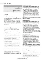
non-contact voltage detector
•
Set the rotating switch to the EF- mode. The
green LED lights up.
•
Place the sensor near the measured area. If
the device detects voltage, the red LED will
blink and the device beeps. (In this mode the
automatic power off and backlight functions
do not work).
Voltage measuring
Warning: to avoid electric shock and damage to the
device, never exceed 1000V dC or 750V aC!
•
Set the function switch to V (VAC or VDC)
mode.
•
Press the „RANGE” button for manual range
selection.
•
Connect the black measuring wire to the
„COM” connector, and the red one to the V
connector.
•
Connect the other ends of the wires to the
measured circuit or signal source.
•
Read the measured value from the screen.
resistance measuring
Warning: to avoid electric shock and damage to the
device, disconnect the power source of the measured
circuit and discharge all capacitors before measuring!
•
Set the function switch to Ω
•
Connect the black measuring wire to the
„COM”connector and the red one to the VΩ
connector.
•
Connect the wires to the end points of the
resistor.
•
Read the measured value from the screen.
note: When measuring above 1mΩ the device may need a
few seconds for stable results.
if the measured circuit is open, the display will show „Ol”.
Continuity measuring
Warning: to avoid electric shock and damage to the
device, disconnect the power source of the measured
circuit and discharge all capacitors before measuring!
•
Set the rotating switch to
mode.
•
Press the „FUNC” button to set the mode.
•
Connect the black measuring wire to the
„COM” and the red one to the „Ω” connector.
•
Connect the other end of the wires to the
measured circuit. If the resistance between
the two points is lower than 40Ω, the device
beeps.
note: continuity test is also available for verifying whether
a circuit is open/closed.
diode measuring
Warning: to avoid electric shock and damage to the
device, disconnect the power source of the measured
circuit and discharge all capacitors before measuring!
•
Set the rotating switch to
mode.
•
Press the „FUNC” button to set the mode.
•
Connect the black measuring wire to the
„COM” and the red one to the „Ω” connector.
•
Connect the red wire to the diode's anode and
the black one to the cathode.
•
The display shows the opening voltage of the
diode. If you accidentally switched the polarity,
the display will show „OL”.
Capacity measuring
Warning: to avoid electric shock and damage to the
device, disconnect the power source of the measured
circuit and discharge all capacitors before measuring!
•
Set the rotating switch to -||-mode.
•
Connect the black measuring wire to the
„COM” and the red one to the „-||-” connector.
•
Connect the other end of the wires to the
measured capacitors and read the value from
the screen.
note: the device may need a few seconds (30 seconds at
200μF) for a stable result. For an accurate result under 4nF
subtract the remaining capacity between the multimeter
and the measuring wires from the end result.
Frequency measuring
•
Set the rotating switch to Hz mode.
•
Connect the black measuring wire to the
„COM” connector and the red one to the „Hz”
connector.
•
Connect the multimeter to the circuit and read
the frequency value from the display.
note: measurement above 3V rms is possible, but the
accuracy is not guaranteed.


