background image

Name

Description

PtN

Set program Pattern

Set pattern “1” at first for 8 segments then set pattern 
“2’” for other 8 segments, pattern 1 & 2 can be 
performed separately or be linked to make total 16 
segments (steps). If it needs to link, set “PIN” to “0”
after pattern 1& 2 be set. Range of setting : 0-2

SEG

Program segment display

Range of setting : (1-0)~(2-8)

tMEr

Program timer display

Process time display only

SV-1

Set volume for seg.1

Range of setting : LSPL - USPL

tM-1

Set time for seg.1

Range of setting : 0~99 hours 59 min

OUT1

Set output for Seg.1

Range : 0~100%

SV-2

Set volume for seg.2

Range of setting : LSPL - USPL

tM-2

Set time for seg.2

Range of setting : 0~99 hours 59 min

OUT2

Set output for Seg.2

Range : 0~100%

SV-3

Set volume for seg.3

Range of setting : LSPL - USPL

tM-3

Set time for seg.3

Range of setting : 0~99 hours 59 min

OUT3

Set output for Seg.3

Range : 0~100%

SV-4

Set volume for seg.4

Range of setting : LSPL - USPL

tM-4

Set time for seg.4

Range of setting : 0~99 hours 59 min

OUT4

Set output for Seg.4

Range : 0~100%

SV-5

Set volume for seg.5

Range of setting : LSPL - USPL

tM-5

Set time for seg.5

Range of setting : 0~99 hours 59 min

OUT5

Set output for Seg.5

Range : 0~100%

SV-6

Set volume for seg.6

Range of setting : LSPL - USPL

tM-6

Set output for Seg.6

Range of setting : 0~99 hours 59 min

OUT6

Compensate PV

Range : 0~100%

SV-7

Set volume for seg.7

Range of setting : LSPL - USPL

tM-7

Set time for seg.7

Range of setting : 0~99 hours 59 min

OUT7

Set output for Seg.7

Range : 0~100%

SV-8

Set volume for seg.8

Range of setting : LSPL - USPL

tM-8

Set time for seg.8

Range of setting : 0~99 hours 59 min

OUT8

Set output for Seg.8

Range : 0~100%

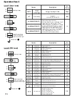
Operating display

Program level :

Press the            key

Repeat the same steps 
as above to display the 
parameters listed at right.

27.5

27.5

PV

SV

OUTL

100.0

PV

SV

SET

At

no

PV

SV

Press the            key

SET

AL1

0.0

PV

SV

Press the            key

SET

AL2

0.0

PV

SV

Press the            key

SET

AL3

0.0

PV

SV

Return to “

Ptn

1

PV

SV

Press the            key

SET

SEG

1

PV

SV

Press the            key

SET

P.6

Press the            key

SET

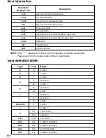
Содержание MC-2438

Страница 1: ...MC 2 SERIES OPERATION MANUAL MAXTHERMO MAXTHERMO GITTA GROUP CORP GITTA GROUP CORP Version Version 0711070001 0711070001...

Страница 2: ...cification Error information Error information Input selection table Input selection table Alarm selection table Alarm selection table P 1 P 2 P 3 P 7 P 11 P 11 P 12 P 17 Alarm action description Alar...

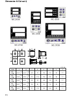
Страница 3: ...44 5 44 5 65 70 50 50 80 17 MC 2538 44 5 90 5 111 116 50 96 80 17 MC 2638 90 5 44 5 65 70 96 50 80 17 MC 2738 68 5 68 5 89 94 74 74 80 17 MC 2838 90 5 90 5 111 116 96 96 80 17 A C D B F E H G unit mm...

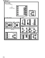
Страница 4: ...Output1 action indication 1 1 PV Process value display 9 9 OUT 2 Output2 action indication 10 10 AT Auto tuning action indication 2 2 SV Set value 11 11 AL 1 Alarm1 action indication 3 3 SET Set key e...

Страница 5: ...tuning off set Range of setting 0 100 F S 0 CYT1 Main Control Output cycle time When output is SSR it is set at 3 4 20 mA is set at 1 but output is relay usually it is set at 20 Range of setting 0 100...

Страница 6: ...utput only 400 CHO1 Output1 span set Calibrate the high value of output1 Range of setting 0 2000 current output only 2000 OPrL Transmitter zero set Calibrate the low value of transmitter Range of sett...

Страница 7: ...0 the parameter is skipped If the digit set at 1 the parameter is opened PrOG 0 Program no repeat 1 Program repeat 0 Without power failure 1 With power failure 0 Start from 0 1 Start from PV 0 Alarm...

Страница 8: ...of setting LSPL USPL tM 4 Set time for seg 4 Range of setting 0 99 hours 59 min OUT4 Set output for Seg 4 Range 0 100 SV 5 Set volume for seg 5 Range of setting LSPL USPL tM 5 Set time for seg 5 Rang...

Страница 9: ...OH time it is loop open 3 Program It doesn t need installing hardware but has to modify software as following steps a Open MODE in level 4 and set mode 3rd 4th digit to 01 then the parameter of proces...

Страница 10: ...ogram will perform again from stopped segment when the power is recovered On the contrary if the PROG 1st digit set 0 it hasn t power failure function the program always perform again from first segme...

Страница 11: ...to 01 in level4 to open motor valve control function d Set CYT1 to open close cycle time of motor valve in level2 and RUCY to time from open to close of motor valve in level3 e The LED bar on the pan...

Страница 12: ...2438 series don t have this function SET A M A M P 10 1 I 1 Input Main nput Main 1 T C Thermocouple S B R K E J W N Cu or PT100 selectable 2 DC V 10 10mV 0 10mV 0 20mV 0 50mV 0 1V 0 5V 0 10V selectab...

Страница 13: ...failed AutF Auto tuning failed NOTE If the marked error occurs the Temperature Controller need repair Please send it to the nearest sales office or retail dealer Error information Error information T...

Страница 14: ...13 Deviation high low limit alarm NO 04 14 Dand alarm NO 05 Absolute value high limit alarm YES 15 Absolute value high limit alarm NO 06 Absolute value low limit alarm YES 16 Absolute value low limit...

Страница 15: ...Option A Power Supply B Control Output C Input D Alarm F Communication Relay SSR mA V Relay SSR Proportional Motor Valve Control OUT1 Option CLOSE OPEN COM AL1 AL2 OUT1 OUT2 mA V RTD TC mV Use OUT1 O...

Страница 16: ...MC 2738 AC 85 265V DC 15 50V Option A Power Supply B Control Output C Input D Alarm E Retransmission F Remote G Communication Relay SSR mA V Relay SSR OUT1 OUT2 NO NC COM mA V RTD TC mV TRS NO COM NC...

Страница 17: ...538 MC 2638 AC 85 265V DC 15 50V Option A Power Supply B Control Output C Input D Alarm E Retransmission G Communication F Remote Relay SSR mA V Relay SSR OUT1 OUT2 OUT1 Option Proportional Motor Valv...

Страница 18: ...18 19 20 12 13 11 4 5 3 6 7 14 15 MC 2838 AC 85 265V DC 15 50V Option A Power Supply B Control Output C Input D Alarm G Communication F Remote OUT1 OUT2 Relay SSR mA V Relay SSR Proportional Motor Va...

Страница 19: ...HIGH OFF ON LOW HIGH OFF ON LOW HIGH OFF ON 06 Absolute low alarm inhibit 16 Absolute low alarm no inhibit 07 Segment end alarm use for Program Model only 1 ALD1 3 set 07 2 AL1 3 alarm segment No set...

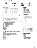
Страница 20: ...phase SCR A 0 5V B 0 10V C 1 5V C C Out 2 control output mode for cooling Out 2 control output mode for cooling 0 None 1 Relay contact SPDT 5A 240VAC 2 SSR Voltage pulse 20VDC 20mA 3 Current 4 20mA A...

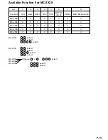
Страница 21: ...VE MC 2438 V V V V V V V MC 2538 V V V V V V V V MC 2638 V V V V V V V V MC 2738 V V V V V V V MC 2838 V V V V V V V V MC 2438 1 6 select 1 4 6 select 1 2 5 7 8 select 1 MC 2738 1 6 select 1 2 4 selec...

Отзывы: