Extended AT Commands Manual
Page 28 of 70
2009-06-25
6 .
D I A G N O S T I C C O M M A N D S
These commands are used for testing and diagnostic purposes. They can not be used in the
calling state.
6.1.1.1.
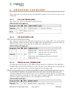
Ring test (AT$$DIAG_RING)
This command is used to confirm MT2 ring alert function.
Table 6-47 Execute Command
Command TE2
Æ
MT2
$$DIAG_RING=<value>
Response
TE2
Å
MT2
$$DIAG_RING: 1 | 0 (Success | Failure)
Value
1 – 20000 Ringing time in sec
0: stop test
6.1.1.2.
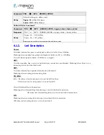
LED test (AT$$DIAG_LED)
NOTE: This function incorporates a soft power reset.
This command is used to check MT2 LED lamps function and requires MT2 to be in the off-line
command state. All LED are tested apart from PWR. After command has been issued the LED are
turned off, then come on one by one. This is followed by a soft power reset.
Table 6-48 Execute Command
Command TE2
Æ
MT2
$$DIAG_ LED=1
Response
TE2
Å
MT2
$$DIAG_LED: 1 (response back when test starts)
$$DIAG_LED: (response when the tests finishes)
OK
(Modem resets power)
(After power up the following notification is effected)
$$TELSTRA 3G
6.1.1.3.
RSSI LED response (AT$$RSSI_LEVEL)
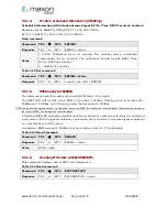
The command is used to read or set the RSSI values governing the performance of the RSSI LED.
The RSSI LED will be OFF when RSSI is less than the lower_value, flashing when in-between the
upper_value and the lower_value, and ON when greater that the upper_value.
NOTE: the higher the negative number i.e. the further away from ZERO, the weaker the received signal. The smaller the number i.e.
the closer to ZERO, the stronger the received signal. Therefore lower_value refers to a weaker signal than upper_value.
A flashing RSSI LED when default values are set indicates potential need for an alternative
antenna, relocating the antenna to a site more suited to signal acquisition, or elevation of the
antenna to improve signal acquisition, or a combination of all the above.
Table 6-49 Read Command
Command TE2
Æ
MT2
$$RSSI_LEVEL?
Response
TE2
Å
MT2
$$RSSI_LEVEL: <upper_value>, <lower_value>


