background image

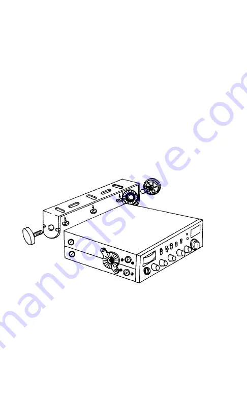
3. Determine the mounting location of the radio.

4. Use the U-shaped mounting bracket as a template

for marking the location of the screw holes.

CAUTION: Extreme care should be exercised when

drilling up into the dash

 to avoid damage to in-dash

electronic ignition wiring, cruise control, instruments,

air lines or accessory wiring.

5. Drill the necessary holes and secure the U-shaped

mounting bracket with self-tapping screws (fig. 8).

6. Position the CB unit between the mounting bracket

arms (fig. 8) and adjust to the desired viewing angle.

Secure by tightening the two retention knobs.

fig. 8

7. Install the microphone hanger bracket into the

pre-drilled mounting holes on either side of the

MCB-100 WXD cabinet 

or

 attach the bracket to the

vehicle dash or any other convenient location.

NOTE:

 If you choose to mount the CB in a location

where self-tapping screws cannot be used, determine

the most secure method of fastening the U-shaped

mounting bracket to that surface.

8

Содержание MCB-100 WXD

Страница 1: ...MCB 100 WXD Professional 40 Channel Mobile CB Weather Radio OWNER S MANUAL Downloaded from www cbradio nl ...

Страница 2: ...Loop Synthesizer Operating Temperature 30o C to 50o C Input Voltage 13 8V DC nominal negative or positive ground Channel Display Light Emitting Diode LED DC Input Power 5 W Dimensions 7 W x 7 3 8 D x 2 H Weight 2 lbs 9 3 oz External Speaker optional 4 W output 4 Ohms with 3 5 mm plug RECEIVER Receiving System AM Dual conversion superheterodyne Audio Output Power 4 W 10 THD TRANSMITTER RF Output Po...

Страница 3: ...l 40 Channel Mobile CB Weather Radio Maxon s MCB 100 WXD is designed for either in dash or under over dash installation easy operation and is one of the most reliable 40 channel Citizens Band weather radios available Package Contents Main CB unit Deluxe handheld microphone CB Unit and microphone mounting hardware In dash mounting collar In dash faceplate trim ring In dash rear support mounting str...

Страница 4: ...tem Connection Mobile Antenna Information Antenna Tuning SWR Meter Operation Calibrating the SWR Meter Standing Wave Ratio Chart Operating Instructions For CB Operation To Transmit To Receive External Speaker Operation PA System and Optional PA Speaker Operation Using the Weather Receiver Weather Operation Radio Communication Codes CB Channel Frequency Chart Troubleshooting Chart Warranty Statemen...

Страница 5: ...nel selector knobs Dual color LED identifies transmit and receive modes Public Address PA system circuitry speaker not included Automatic Noise Limiter ANL and noise blanker circuitry switch reduces atmospheric static noise interference during CB operation and reduces electrical impulse noise caused by the vehicle s ignition SWR Meter calibration capability RF Gain control knob adjusts the receivi...

Страница 6: ...on selects noise blanker with automatic noise limiter circuitry ANL circuitry only or off N CH 9 NOR CH 19 Switch Position selects Emergency CH 9 normal CB channels 1 40 or Highway CH 19 O S RF SWR CAL Switch Position selects function of analog meter measuring radio input output signal power strength measuring Standing Wave Ratio of antenna or entering SWR calibration mode P Front mounted Deluxe M...

Страница 7: ...3 MOBILE CB RADIO A B C D E F G Q P O N M L K J I H ...

Страница 8: ...ioning Wiring instruc tions for power and antenna are located in this manual The radio s power and antenna connecting cables must be routed and secured in such a manner as not to interfere with the operation of the brake accelerator or other controls Interference from either the CB unit or its connecting cables may contribute to the loss of control of the vehicle Hardware is provided for in dash o...

Страница 9: ...he radio fig 1 They lock the CB unit securely into the mounting collar fig 1 1 Before inserting the mounting collar into the dash push the side tabs inward with a slight pressure fig 2a Insert the mounting collar into the dash board opening fig 2b Select the proper tabs according to the thickness of the dashboard material fig 3 and bend them up slightly for a secure hold fig 2a fig 2b fig 3 5 ...

Страница 10: ...ceplate trim ring around the face of the CB unit Insert the faceplate trim ring tabs into the grooves on the bottom of the CB unit Then slide the top side of the faceplate trim ring back into position and snap tabs securely into grooves 4 Mount the microphone hanger bracket wherever it is most convenient Removing the In Dash CB Unit 1 Remove the front faceplate trim ring by lifting the tabs on the...

Страница 11: ...ly pull the CB unit forward fig 5 fig 5 Under Over Dash Installation Under over dash installation requires the following provided hardware U shaped mounting bracket locking washers retention knobs microphone hanger bracket and self tapping screws 1 REMOVE the factory pre installed screws on both sides of the CB unit fig 6 fig 6 2 Install one locking washer on each side with grooves facing away fro...

Страница 12: ...mounting bracket with self tapping screws fig 8 6 Position the CB unit between the mounting bracket arms fig 8 and adjust to the desired viewing angle Secure by tightening the two retention knobs fig 8 7 Install the microphone hanger bracket into the pre drilled mounting holes on either side of the MCB 100 WXD cabinet or attach the bracket to the vehicle dash or any other convenient location NOTE ...

Страница 13: ...IRE FASTEN TO METAL FASTEN TO METAL BODY BODY OF VEHICLE OF VEHICLE EXAMPLE OF NEG GROUND 12V DC EXAMPLE OF POS GROUND 12V DC BATTERY CONNECTION MOST BATTERY CONNECTION FEW COMMERCIAL VEHICLES ARE THIS TYPE COMMERCIAL VEHICLES ARE THIS TYPE Your MCB 100 WXD should be connected using the following steps Place the on off volume knob in the off position by turning it counter clockwise to detent Unplu...

Страница 14: ...the ignition is turned off NOTE Be sure the metal part is not insulated from the vehicle s frame by a plastic part 2 Connect the red to switched accessory wire to a source of voltage that turns on and off with the ignition switch such as a spare accessory terminal in your vehicle s fuse box 3 Connect the orange GROUND wire to a metal part of your vehicle s frame This connection provides last chann...

Страница 15: ... installing a mobile antenna please follow the antenna manufacturer s installation instructions completely Never operate your CB radio without an antenna or with a broken antenna cable This can result in internal damage to your CB circuitry Connect the antenna securely to the unit s antenna receptacle Mount the antenna as high on the vehicle as possible the more the antenna extends above the roof ...

Страница 16: ...ar channel preference set your antenna s SWR for maximum performance for Highway Channel 19 operation You will obtain a different SWR reading from one CB channel to another If you use all 40 CB channels you may have 40 different SWR readings Usually almost all the CB transmissions will fall within an acceptable range Calibrating the SWR Meter To calibrate the SWR meter place the S RF SWR CAL switc...

Страница 17: ...umidity corrosion etc or vehicle vibration can cause degradation in performance This may be indicated by a rise in the SWR meter s normal reading Check the antenna s condition and the coaxial cable RF electrical connections etc if a problem is indicated 13 ...

Страница 18: ...Higher than Inefficient 3 1 PERFORMANCE Perfect match between the antenna and cable length to the CB radio transmitter s RF output power The antenna cable system is an outstanding match with this CB transmitter s RF output power ideal for most CB installations The antenna cable system with this CB transmitter will perform to spec under most normal conditions Requires antenna system s mountinghardw...

Страница 19: ...to prevent damage to the microphone cord For CB Operation 1 Turn the power on and adjust the volume to the desired listening level Set the CB PA switch to the CB position and the CB WX mode selector knob to the CB mode position NOTE Verifythat the CH 9 NOR CH 19 switch is in the NOR normal position and the S RF SWR CAL switch is set to S RF 2 Use the CB channel selector knob to select the desired ...

Страница 20: ... standing by the RX TX LED will glow green External Speaker Operation To connect an optional external speaker locate the external speaker jack on the rear of the unit and insert the speaker plug into the jack The radio s internal speaker will be silenced when an external speaker is engaged PA System and Optional PA Speaker Operation To use the Public Address system feature you must install a PA sp...

Страница 21: ...signed to receive all seven NOAA weather frequencies as well as 3 periodic international marine weather frequencies A frequency reference card of the National Oceanic and Atmospheric Administration NOAA Weather Radio Network is enclosed with your radio The MCB 100 WXD receives the following CB and National Weather Service frequencies CB Channels 1 40 26 965 to 27 405 MHz Weather Channels 1 162 550...

Страница 22: ...cate the proper weather channel for your current geographic location The WX LED will glow green when the weather receiver is active Re adjust the volume if necessary To resume normal CB operation simply turn the CB WX selector to the CB position 18 ...

Страница 23: ...________ 10 39 Your message delivered 10 41 Please turn to channel______ 10 42 Traffic accident at__________ 10 43 Traffic tie up at_____________ 10 44 I have a message for you 10 45 All units within range report 10 50 Break channel 10 60 What is next message number 10 62 Unable to copy use phone 10 63 Network directed to 10 64 Network clear 10 65 Awaiting your next message assignment 10 67 All un...

Страница 24: ... 175 MHz 27 185 MHz Highway Channel 27 205 MHz 27 215 MHz 27 225 MHz 27 255 MHz 27 235 MHz 27 245 MHz 27 265 MHz 27 275 MHz 27 285 MHz 27 295 MHz 27 305 MHz 27 315 MHz 27 325 MHz 27 335 MHz 27 345 MHz 27 355 MHz 27 365 MHz 27 375 MHz 27 385 MHz 27 395 MHz 27 405 MHz CB CHANNEL FREQUENCY CHART 1 2 3 4 5 6 7 8 9 10 11 12 13 14 15 16 17 18 19 20 21 22 23 24 25 26 27 28 29 30 31 32 33 34 35 36 37 38 3...

Страница 25: ...nal adjustments and or modifications can lead to illegal operation as defined by FCC Rules and Regulations Part 95 Illegal operation can result in serious consequences CAUTION The fuse included with this unit is an important safety feature which must not be circumvented Removal of this fuse or the use of a fuse rated higher than supplied may result in overheating and or fire and consequential dama...

Страница 26: ...e of the original time period All replaced parts accessories batteries or boards become the property of Maxon America Inc Maxon shall have no obligation to make repairs or to cause replacement required which result from normal wear and tear or is necessitated in whole or in part by catastrophe the fault or negligence of the user improper or unauthorized alterations repairs to the Product incorrect...

Страница 27: ...and Thank you for choosing Maxon For more information contact Maxon America Inc Consumer Products Division 10828 NW Air World Drive Kansas City Missouri 64153 Phone 1 800 821 7848 Ext 399 Fax 816 891 8815 or explore our website www maxonusa com ...

Отзывы: