Low temperature burners - INDITHERM
®
w w w . m a x o n c o r p . c o m
combustion systems for industry
MAXON reserves the right to alter specifications and data without prior notice.
© 2008 Copyright Maxon Corporation. All rights reserved.
1 - 2.3 -
10
E - m - 7/08
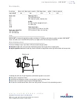
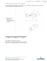
Control motor mounting plate
The INDITHERM
®
burner can be equipped with an electrical or pneumatic control motor for capacity control. A broad range of
mounting plates are available to accept almost any common control motor on the market. Required torque = 1.2 Nm.
Maximum capacities
INDITHERM
®
burners will have different maximum capacities depending on burner size and application back pressure.
Refer to table on page 1-2.3-6 for maximum capacities.
Capacities are stated for firing at zero back pressure and for 1.5 mbar back pressure, both at 3 % O
2
level in the exhaust gases.
Minimum capacities
The minimum capacities depend on burner size and can be found in the table at page 1-2.3-6. The capacities in this table are those
that still allow a stable flame on main gas. When lower capacities are required, using a continuous pilot can be a solution. In this
case, the internal gas control valve of the burner can be closed even more at minimum position, while the minimum required gas
flow to maintain a stable flame can be adjusted using a needle valve on the pilot gas.
Preheated air
The INDITHERM
®
burner is designed to operate with non preheated combustion air. Although, the burner materials are suitable to
withstand up to 200° C temperatures, the burner will not perform according to the specifications page page 1-2.3-6 when the
combustion air is preheated. Contact MAXON for more details.
Process temperature
The high temperature refractory block permits operation of combustion chamber temperatures up to 950 °C . When using a
standard discharge sleeve, proper circulation of cold process air around the entire discharge sleeve should be present at all times.
Piloting and ignition
INDITHERM
®
burners have an internal pilot burner. Piloting is accomplished by internally bypassing the built-in gas butterfly valve
which is in the minimum position at low fire. The pilot gas is admitted to the gas nozzle via the main gas conduit and is injected
through the same gas nozzle ports as the main gas. The pilot gas adjusting valve allows for easy and precise adjusting of the pilot
flame.
The use of an intermittent pilot is technically possible on this burner and could result in lower minimum capacities.
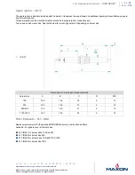
Use minimally 5000 V/200 VA ignition transformers for sparking of the spark ignitor. Locate pilot gas valves as close as possible
to the pilot burner gas inlet, to have fast ignition of the pilot burner. When igniting the main gas, the capacity rating of the burner at
that point shall be limited.
Direct ignition
In case the use of a pilot burner is not required, the INDITHERM
®
burner can be direct ignited on main gas.
The pilot gas inlet should be plugged. When direct igniting an INDITHERM
®
burner, the capacity setting during ignition should be
limited. Direct ignition at high capacity is not allowed.
Typical ignition sequences
Pre purge of burner and installation, according to the applicable codes and the installation’s requirements.
Burner capacity control valve shall be in the start position to allow minimum combustion air flow to the burner.
Pre-ignition (typically 2 s sparking in air).
Open pilot gas and continue to spark the igniter (typically 5 s).
Stop sparking, continue to power the pilot gas valves and start flame check.
Check pilot flame stability (typical 5 s to prove the stable pilot).
Open main gas valves and allow enough time to have main gas in the burner. (typical 5 s + time required to have main gas in
the burner).
Close the pilot gas valves.
Release to modulation (allow modulation of the burner).
Above sequences shall be completed to include all required safety checks during the start-up of the burner (process & burner
safeties).


