


EtherCAT Communication
Communication Specifications
EPOS4 Communication Guide
4-42
CCMC | 2019-11 | rel8759
4.1
Communication Specifications
Table 4-15
EtherCAT communication – Communication specifications
4.2
EtherCAT State Machine (ESM)
The EtherCAT State Machine coordinates both Master and Slave during startup and operation. Their inter-
action (Master
Slave) results in changes of states being related to writes to the Application Layer Control-
word: AL Ctrl (0x0120).
Upon initialization of Data Layer and Application Layer, the ESM enters “Init” state which defines the Appli-
cation Layer's root of the communication relationship between Master and Slave. In the Application Layer,
no direct communication between Master and Slave is possible. The Master uses “Init” state…
•
to initialize a configuration register set and
•
to configure the Sync Manager.
Operation of the connected EPOS4 (the Slave) requires its prior initialization by the Master via the ESM.
Within the ESM, transitions between certain states must follow a given scheme and will be initiated by the
Master. The Slave itself must not execute any transition.
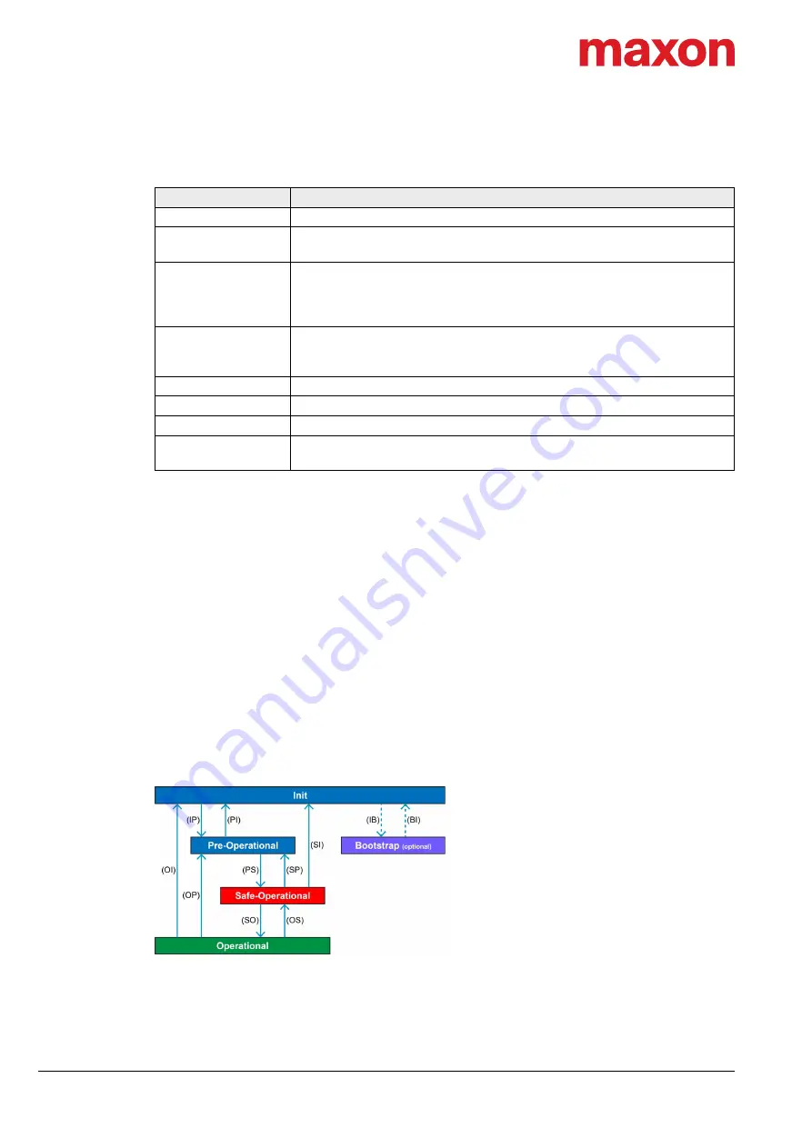
For an overview of the EtherCAT State Machine
Figure 4-39, for further descriptions
as from
Figure 4-39
EtherCAT communication – ESM scheme
Topic
Description
Physical layer
IEEE 802.3 100 Base T (100 Mbit/s, full duplex)
Fieldbus connection
X14 (RJ45): EtherCAT Signal IN
X15 (RJ45): EtherCAT Signal OUT
SyncManager
SM0: Mailbox output
SM1: Mailbox input
SM2: Process data outputs
SM3: Process data inputs
FMMU
FMMU0: Mapped to process data output (RxPDO) area
FMMU1: Mapped to process data input (TxPDO) area
FMMU2: Mapped to mailbox status
Process data
Variable PDO mapping
Mailbox (CoE)
SDO Request, SDO Response, SDO Complete Access
Synchronization
SM-synchron, DC-synchron
LED indicators
NET status (green LED / red LED)
NET port activity (green LED)


