background image

maxon motor control
MCD EPOS P Programmable Compact Drive

Document ID: rel2895    

Z-27

MCD EPOS P 60 W Hardware Reference

Edition: December 2011

© 2011 maxon motor. Subject to change without prior notice.

A

additionally applicable regulations


10

alerts


5

B

backup power


17

C

cable

325235


16

325939


16

326923


19

326925


16

calculation of required supply voltage


16

CAN

interface


18

connector

J1


19

J2


16

country-specific regulations


10

D

digital inputs


20

22

digital outputs


23

E

electrical data


11

environmental conditions, permitted


13

error display


24

ESD


10

example

wiring proximity switches


21

H

how to

calculate required supply voltage


16

interpret icons (and signs) used in the document


5

I

informatory signs


6

interface

CAN


18

RS232


18

interfaces, location and designation


15

L

LEDs


24

M

mandatory action signs


6

mechanical data


13

motor data


11

O

operating status, display


24

P

performance data


11

power backup


17

precautions


10

prohibitive signs


6

purpose

of this document


5

R

regulations, additionally applicable


10

RS232

interface


18

S

safety alerts


5

safety first!


10

signs

informative


6

mandatory


6

prohibitive


6

signs used


5

status display


24

status LEDs


24

supply voltage, required


16

symbols used


5

T

technical data


11

I

NDEX

Содержание MCD EPOS P 60 W

Страница 1: ...H 6072 Sachseln Phone 41 41 666 15 00 Fax 41 41 666 15 50 www maxonmotor com Edition December 2011 MCD EPOS P Programmable Compact Drive Hardware Reference maxon motor control 60 W Programmable Compac...

Страница 2: ...things you already know Likewise we tried to skip repetitive information Thus you will find things mentioned just once If for example an earlier mentioned action fits other occasions you then will be...

Страница 3: ...2 Electrical Data 11 3 3 Mechanical Data 13 3 4 Environmental Conditions 13 3 5 Order Details 14 4 Connections 15 4 1 Power Communication Connector J2 16 4 1 1 Power Supply 16 4 1 2 Logic Supply opti...

Страница 4: ...Document ID rel2895 MCD EPOS P Programmable Compact Drive Edition December 2011 MCD EPOS P 60 W Hardware Reference 2011 maxon motor Subject to change without prior notice p a g e i n t e n ti o n a l...

Страница 5: ...et Audience This document is meant for trained and skilled personnel working with the equipment described It con veys information on how to understand and fulfill the respective work and duties This d...

Страница 6: ...to avoid a hazard So you must Examples 1 4 3 Informatory Signs Requirement Note Remark Indicates an action you must perform prior continuing or refers to information on a particular item Best Practice...

Страница 7: ...ument Table 1 2 Brand Names and Trademark Owners 1 6 Copyright 2011 maxon motor All rights reserved The present document including all parts thereof is protected by copyright Any use including repro d...

Страница 8: ...Document ID rel2895 MCD EPOS P Programmable Compact Drive Edition December 2011 MCD EPOS P 60 W Hardware Reference 2011 maxon motor Subject to change without prior notice p a g e i n t e n ti o n a l...

Страница 9: ...torque ripple and low noise The integrated position velocity and current control functionality allows sophisticated positioning applications The MCD EPOS P 60 W is programmable with a very efficient...

Страница 10: ...endent monitoring and safety equipment If the machine apparatus should break down if it is operated incorrectly if the control unit breaks down or if the cables break or get disconnected etc the compl...

Страница 11: ...4 mm Radial play preloaded Max axial load dynamic 5 5 N Max force for press fits static 100 N Max radial loading projecting 5 mm from flange 25 N Rating Nominal power supply voltage VCC 12 50 VDC Nomi...

Страница 12: ...DC Digital Input 2 Home Switch optically isolated 9 24 VDC Digital Input 3 Positive Limit Switch optically isolated 9 24 VDC Digital Input 4 Negative Limit Switch optically isolated 9 24 VDC Digital I...

Страница 13: ...ons Connections J1 Power On board Suitable plug D Sub connector High Density 15 poles female D Sub connector High Density 15 poles male J2 Power On board Suitable plug D Sub connector 9 poles male D S...

Страница 14: ...MCD EPOS P Programmable Compact Drive Edition December 2011 MCD EPOS P 60 W Hardware Reference 2011 maxon motor Subject to change without prior notice 3 5 Order Details Table 3 13 Order Details Order...

Страница 15: ...e Compact Drive Document ID rel2895 4 15 MCD EPOS P 60 W Hardware Reference Edition December 2011 2011 maxon motor Subject to change without prior notice 4 Connections Figure 4 3 Interfaces Designatio...

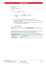
Страница 16: ...nt Known values Operating torque MB mNm Operating speed nB rpm Speed constant kn 393 rpm V Speed torque gradient of the motor n M 20 6 rpm mNm Pin Signal Description 1 EPOS RxD EPOS RS232 receive 2 Gn...

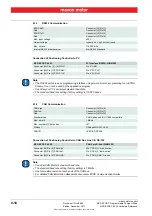
Страница 17: ...power supply observe that the overcurrent protection must not be activated in any operating state 4 1 2 Logic Supply optional By default the logic is powered by the regular supply voltage Optionally y...

Страница 18: ...stor at both ends of the CAN bus For detailed CAN information separate document EPOS Communication Guide EPOS RxD Gnd EPOS TxD Gnd Connector J2 Pin 1 Connector J2 Pin 2 Connector J2 Pin 3 Connector J2...

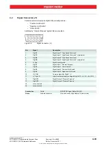
Страница 19: ...N7 Digital Input 7 High Speed Command complement 3 DigIN8 Digital Input 8 High Speed Command 4 DigIN8 Digital Input 8 High Speed Command complement 5 D_Gnd Digital signal ground 6 DigIN1 Digital Input...

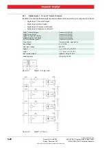
Страница 20: ...put 2 Home Switch Digital Input 3 Positive Limit Switch Digital Input 4 Negative Limit Switch Figure 4 7 DigIN1 4 Logic Level Figure 4 8 DigIN1 4 Circuit DigIN1 General Purpose DigIN2 Home Switch DigI...

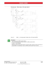
Страница 21: ...tches Figure 4 9 DigIN1 4 Wiring Example for different Types of Proximity Switches Best Practice Preferably use 3 wire PNP proximity switches Using 3 wire NPN proximity switches requires an additional...

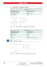
Страница 22: ...IN8 Note Do not connect DigIN s complements Figure 4 11 DigIN7 Single ended Circuit analogously valid also for DigIN8 Differential DigIN7 High Speed Command DigIN8 High Speed Command Connector J1 Pins...

Страница 23: ...By default the optically isolated digital outputs are defined as General Purpose and may be configured via software Figure 4 12 DigOUT3 Circuit analogously valid also for DigOUT4 V Opto IN IN_COM com...

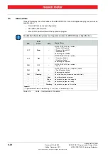
Страница 24: ...mware Specification Table 4 14 LEDs Interpretation of Condition LED Status Error Red Green Blue OFF Slow MCD EPOS P 60 W is in status Switch ON Disabled Ready to Switch ON Switched ON Power stage is d...

Страница 25: ...nd Location 15 Figure 4 4 Wiring Diagram 15 Figure 4 5 Power Communication Connector J2 16 Figure 4 6 Signal Connector J1 19 Figure 4 7 DigIN1 4 Logic Level 20 Figure 4 8 DigIN1 4 Circuit 20 Figure 4...

Страница 26: ...ademark Owners 7 Table 3 3 Motor Data Rating 11 Table 3 4 Electrical Data Rating 11 Table 3 5 Electrical Data Inputs 12 Table 3 6 Electrical Data Outputs 12 Table 3 7 Electrical Data Interfaces 12 Tab...

Страница 27: ...s permitted 13 error display 24 ESD 10 example wiring proximity switches 21 H how to calculate required supply voltage 16 interpret icons and signs used in the document 5 I informatory signs 6 interfa...

Страница 28: ...ncluding all parts thereof is protected by copyright Any use including reproduction translation microfilming and other means of electronic data processing beyond the narrow restrictions of the copyrig...

Отзывы: