VP30/VP500
MAINTENANCE INFORMATION
If the valve plate assembly 6/11 is excessively worn it must be replaced.
Reassemble in reverse order, fitting new gaskets. When reassembling, lubricate every component
(except gaskets) with clean lubricating oil.
On reassembly, tighten the cylinder head screws to the correct torque loading.
3rd Stage Valves
Unscrew the tubing nut adaptors and detach cooler tubes from the cylinder head.
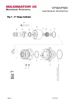
Unscrew and remove vavle retainer 7/15 and locking nut 7/14, together with seal 7/13.
Unscrew and remove caphead screws 7/12 and lift off cylinder head valves 7/11.
Remove valve 7/10 together with seals 7/9 and 7/8.
Carefully clean valves using soft scrapers, (eg. copper, wood, plastic) and petroleum (gasoline) to
remove carbon deposits and dirt.
Clean the cylinder face of 7/7 and clean cylinder head 7/11 thoroughly, removing all traces of
carbon buildup. Ensure that all mating surfaces are clean and smooth.
Clean the mating surface and cylinder bore of the cylinder 7/7and remove the rest of 7/7 above.
Ensure that no dust or dirt particles remain in the cylinder. Use compressed air to blow out if
necessary. If the valve 7/10 is excessively worn it must be replaced.
Seals 7/8, 7/9, 7/13 should always be replaced, to avoid premature leakage. When installing these
seals ensure that they are correctly located around the valves.
Reassemble in reverse order. When reassembling lubricate every component, (except gaskets but
including O-rings) with clean lubricating oil.
To reassemble, locate valve 7/10 into the cylinder head 7/11 with seals 7/8 and 7/9. Mate the
assembly with the cylinder 7/7. Replace the capscrews 7/12, turning 1/16
th
turn at a time in a
diagonal pattern. Tighten to the correct torque loading.
Replace locking nut 7/14 with seal 7/13 and tighten against the valve.
Replace lock-ring 7/15 and tighten.
Re-attach the cooler tubes.
Type of screw
M
Max
M6 screw, quality 8.8
10 Nm
M6 screw, quality 10.9
14 Nm
M8 screw, quality 8.8
24 Nm
M8 screw, quality 10.9
32 Nm
M10 screw, quality 8.8
50 Nm
M10 screw, quality 10.9
70 Nm
M12 screw, quality 8.8
88 Nm
M12 screw, quality 10.9
120 Nm
M12 screw, quality 12.9
130 Nm
Central pressure screw conc. valve
200 Nm
Maximum tightening torques for cylinder head screws and connecting rod screws
July 21
10 of 42
Содержание VP30
Страница 15: ...VP30 VP500 MAINTENANCE INFORMATION Fig 2 Crankcase July 21 15 of 42 ...
Страница 17: ...VP30 VP500 MAINTENANCE INFORMATION Fig 3 Crankcase July 21 17 of 42 ...
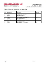
Страница 19: ...VP30 VP500 MAINTENANCE INFORMATION Fig 4 Piston and connecting rod July 21 19 of 42 ...
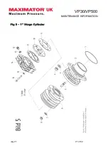
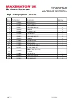
Страница 21: ...VP30 VP500 MAINTENANCE INFORMATION Fig 5 1st Stage Cylinder July 21 21 of 42 ...
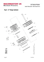
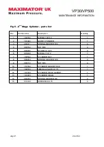
Страница 23: ...VP30 VP500 MAINTENANCE INFORMATION Fig 6 2nd Stage Cylinder July 21 23 of 42 ...
Страница 25: ...VP30 VP500 MAINTENANCE INFORMATION Fig 7 3rd Stage Cylinder July 21 25 of 42 ...
Страница 27: ...VP30 VP500 MAINTENANCE INFORMATION Fig 8 Fan and guard July 21 27 of 42 ...
Страница 29: ...VP30 VP500 MAINTENANCE INFORMATION Fig 9 Coolers July 21 29 of 42 ...
Страница 31: ...VP30 VP500 MAINTENANCE INFORMATION Fig 10 Unloader Manifold July 21 31 of 42 ...
Страница 34: ...VP30 VP500 MAINTENANCE INFORMATION Fig 11 Unloaders July 21 34 of 42 ...
Страница 36: ...VP30 VP500 MAINTENANCE INFORMATION Fig 12 Oil Lubrication July 21 36 of 42 ...
Страница 38: ...VP30 VP500 MAINTENANCE INFORMATION Fig 13 Crankcase Breather July 21 38 of 42 ...
Страница 40: ...VP30 VP500 MAINTENANCE INFORMATION Fig 14 Motor July 21 40 of 42 ...
Страница 42: ...VP30 VP500 MAINTENANCE INFORMATION Fig 15 Microfilter 1 169531 2 101184 3 163140 July 21 42 of 42 ...


