background image

- 5 -

INSTRUCTIONS FOR USE

1. The 

HORNET

Model XTR05 is specifically designed for use in ‘Spin’ Cycle 

classes,  fitness  studios  and  health  clubs.  The  bike  uses  a  fixed  wheel  drive 

flywheel and should only be used with professional supervision or instruction.

2.

Assembly:

It  is  important  that  the  bike  is  correctly  assembled,  and  we 

recommend  that  the  installation  and  assembly  be  undertaken  by  suitably 

qualified  personnel.  Detailed  Assembly  instructions  are  supplied  separately 

with an unassembled bike. If your bike was supplied preassembled follow the 

service  and  maintenance  instructions  later  in  this  manual.  If  you  have 

assembled  the  bike  yourself  ensure  that  all  assembled  procedures  are  correct 

and recheck that all assembled parts are fully tightened. Recheck if necessary.

3.

Location:

The bike should be placed in the desired location and then checked 

that  it  is  both  level  and stable.  Each  ground  tube  has  adjustable  leveling feet

located on the underside of each corner. Ensure that each of the leveling feet 

are in a fully inserted position (Fully rotated CW when viewed from bottom) 

Rotate feet CCW until the bike is both level and stable.

4.

Handlebar And Seat Stem Adjustment

It is important that the handlebar and seat height adjustments are correctly set

for  your  particular  body  dimensions  –  if  you  are  undertaking  any  of  the 

various classes using spin cycles then your instructor will advise you as to the 

correct adjustment procedures relative to the program you are undertaking.

Incorrectly adjusted bikes may produce can produce excessive strain, soreness 

and / or irritation of muscles and joints.

The  instructions  that  follow  are  to  assist  with  bike  set  up 

should you not have an instructor to advise you as to correct 

and proper procedures.

Содержание XTR 05 HORNET

Страница 1: ...IM XTR 05 HORNET SPIN CYCLE Operation Manual Maxim Strength Fitness Equipment Pty Ltd 5 Valetta Road Kidman Park 5025 South Australia Telephone 61 884 433 001 Fax 61 884 433 668 Web www maximfitness n...

Страница 2: ...2...

Страница 3: ...Contents Page 3 2 Preface 4 3 Instructions for use 5 4 Operational Overview 8 5 Service and Maintenance 10 6 Preventative Maintenance Schedule 13 7 XTR 05 Parts Descriptions 14 8 XTR 05 Mk II Parts De...

Страница 4: ...al examination prior to undertaking an exercise program Particularly if the user has a family history of high blood pressure or heart disease Over the age of 45 or smokes High cholesterol obese or has...

Страница 5: ...Location The bike should be placed in the desired location and then checked that it is both level and stable Each ground tube has adjustable leveling feet located on the underside of each corner Ensu...

Страница 6: ...addle apart from indicating an incorrect seating position damages and shortens the life of a saddle Check and make any further adjustment if necessary ii When the saddle height is set adjust the user...

Страница 7: ...mponent Release the lever in its new position and allow the lever to relocate Further rotation and tightening will be possible Lever re positioning can also be used to enable the releasing of a lever...

Страница 8: ...g If you are using the bike in a class environment always follow the instructor s advice If you are riding this style of bike for the first time apply a light brake load and commence pedaling Regulate...

Страница 9: ...riding position and transfer the power from your legs to the pedal without trying to bend your foot over the top of the pedal This is a much more efficient way of power transfer and will help reduce...

Страница 10: ...and completely wipe the handle bars frame and covers Pay attention to the areas where a user will drip sweat particularly internal corners and joints that trap or allow sweat to pool 5 Avoid using pap...

Страница 11: ...re available These are professional tools specifically designed for these applications and must be ordered as spare parts There are tools specifically designed to assist with the removal and tightenin...

Страница 12: ...n and retighten with a spanner or shifter Lift the seat or handle bar and re clamp with the lock lever 3 Grasp the saddle and check if there is any looseness either a tendency to tilt or slide If any...

Страница 13: ...rvice and maintenance facilities that are available to you facility Contact the applicable service department Detail Daily Weekly Monthly Wipe Clean I Wash Clean I Spray with Anti corrosion product I...

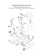
Страница 14: ...14 XTR05 HORNET PARTS LIST To suit the earlier round tube stem version All descriptions on opposite page...

Страница 15: ...Lever M12 2 58 Lock Lever Spacer 2 19 Lock Lever Bush M26 2 59 Belt K4 x 1270 1 20 Flat Washer 16 x 6 x 2t 2 60 Sleeve 240 x 20 1 x 27L 1 21 Bronze Pressure Plate 2 61 B B Axle 25 x 20 x 137 5L 1 22...

Страница 16: ...16 XTR05 HORNET SERIES 2 PARTS LIST To suit the later square tube stem version All descriptions on opposite page Only parts that have changed are shown 13C 13C...

Страница 17: ...iption Qty Part no Description Qty 1 Main Frame 1 11 Handle Bar Assembly 1 12 Lock Lever M12 2 13 Saddle Slider Bottom Plate 1 13A Handle Bottom Plate 1 13B Bolt M6 P1 0 x 35L 1 13C Spring Washer M12...

Страница 18: ...18 2006 02 20 00RJP...

Страница 19: ...19...

Отзывы: