- 12 -
The following detail relates to the simple service procedures referred to in the service
schedule opposite.
1. Lubricate the two lock lever threads (#12) by completely unscrewing
the lock lever. Smear some grease on the tread and return to its original
position.
2. To lubricate the two lock lever threads (#18) firstly release the lock
levers and lower the stems fully. (Do Not Drop) Using a suitable
spanner (28mm or 1
⅛”)
or shifter loosen the nut (#19) and remove the
lock lever assembly completely. Rotate the lever so that a maximum of
thread is exposed on the inner side and smear grease on the thread.
Rotate the lever counter clockwise to expose the maximum of thread
on the outside and smear the exposed thread similarly. Return the
assembly to its original position and retighten with a spanner or shifter.
Lift the seat or handle bar and re-clamp with the lock lever.
3. Grasp the saddle and check if there is any looseness, either a tendency
to tilt or slide. If any movement is detected or if any looseness or
movement in the seat is reported the matter must be attended to as
quickly as is possible. Movement in these areas will damage the seat
mounting mechanism. There are two points to monitor –
a) Socket head screws (4mm key) either side of the saddle clamp
(#26) must be tightened so that the saddle rails are held firmly.
The preferred position is centrally on the two seat rails. This
adjustment controls a fixed fore / aft movement of the saddle.
b) The socket head screw (6mm key) (#25) controls rotational or
the tilting movement of the seat. If a seat has rotated (tilted) –
Firstly loosen the clamp screw (#25) then correct the seat
attitude - preferred position is horizontal. When realigned
correctly, firmly retighten the clamp screw (#25)
Содержание XTR 05 HORNET
Страница 2: ...2...
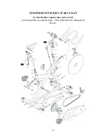
Страница 14: ...14 XTR05 HORNET PARTS LIST To suit the earlier round tube stem version All descriptions on opposite page...
Страница 18: ...18 2006 02 20 00RJP...
Страница 19: ...19...


