


/
IV. SPECIAL FEATURES:
95% preassembled ARF with prepainted Townend Ring
and dummy engine.
Scale looking landing gear with mains wheels fully
enclosed by prepainted fiberglass wheel pants.
Includes a realistic looking windshield, steerable tail
wheel and stick-on scale markings.
The two-piece wing has detachable top struts; the lower
wing’s wing wires may remain attached whenever the
wing is removed for transport and storage.
Fuselage, wings and empennage are jig-assembled,
laser-cut balsa and light plywood.
The semi-symmetrical wing is optimized for excellent
sport-scale aerobatic performance.
The light-weight design has built-in cooling airflow for efficient electric-power operation.
V. SPECIFICATIONS:
Wingspan ....................................................................................................................................... 59 inches
Wing area .......................................................................................................................... 529 square inches
Length ...................................................................................................................................... 41 1/2 inches
ARF weight .................................................................................................................... 3 pounds 10 ounces
Power system ....... 400 to 600 Watt motor and 60A ESC, or as recommended by the maker of your motor
Propeller ............... 11 or 12 inch dia. x 6 or 7 inch pitch, or as recommended by the maker of your motor
Radio ....................................................................................................................... Minimum of 4 channels
Servos ................................................................................................................................. 4 ea. mini servos
(Dimensions and weight are approximate.)
VI. ASSEMBLY INSTRUCTIONS:
1.
Fuselage-Mounted Servos
–
a.
Using hardware supplied with your servos, install the rudder and
elevator servos in their servo tray.
b.
Connect the EZ Link connectors to the servo arms. Guide the EZ Link
connectors onto the rudder and elevator pushrods. (Do NOT tighten
the EZ Link connectors onto the pushrods at this time.) Mount the
servo arms onto the servos. Connect the servos to your receiver and
position the receiver under or behind the servos.
2.
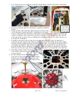
Motor and Dummy Engine
–
a.
This airplane is designed for a Uranus 35425 motor. However, since you may
have your own motor preference, we provide wooden spacers to help fit other
motors. Determine how many spacers may be required behind the motor and/
or the dummy engine by test fitting the motor to the firewall, placing the
dummy engine over the motor, and using spacers to adjust the motor and/or
the dummy engine to bring the prop. backplate approx. 1/4 inch in front of the
dummy engine. Attach any required spacers to the firewall with CA adhesive.
b.
Use the hardware provided with your motor to secure the motor to the
firewall. Apply threadlock compound to protect your motor mounting
bolts from vibration. If necessary, cut off and discard the ends of any bolts
that may be projecting behind the firewall, into the battery compartment.
Page 4 of 12
S121029 Copyright 2012
*
*