


/
8.
Finishing Touches
–
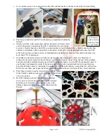
a.
The lower-wing wires are ‘cosmetic’ and designed only for appearance. If you install the lower-wing
wires, select one of the following options:
Option #1 –
Using 5/16-inch wood screws, attach one end of
a swivel with an attached spring and wing wire to
the bottom edge of the root rib. Direct the wing
wire into and through the wheel pant. Drive a 2
nd
screw into the lower-wing spar at the 3
rd
rib from
the wheel pant, wrap the wing wire around the 2
nd
screw, direct it into and through the wheel pant,
and attach it to the spring. Install a wing wire on
the remaining wing panel in the same manner.
Option #2 –
Using 5/16-inch wood screws, attach one end of a
wing wire to the trailing edge at the 3
rd
rib outboard
of the wheel pant. Direct the wing wire into and
through the wheel pant. Drive a 2
nd
screw into the
bottom edge of the root rib, wrap the wing wire
around the 2
nd
screw, and direct it into and through
the wheel pant. Drive a 3
rd
screw into the 3
rd
rib
outboard of the wheel pant and attach one end of a
swivel with an attached spring. Attach the wing
wire to the loose end of the spring. Install a wing
wire on the remaining wing panel in the same manner.
b.
Use 5/16-inch wood screws to hold the windshield in
position directly in front of the cockpit.
c.
If desired, you may also
use epoxy and a
Popsicle stick or other
scrap wood or plastic to
install an optional
Maxford USA 1/5-scale
pilot figure in the
cockpit.
d.
Trim the supplied stick-on markings as necessary. Peel and apply each of the markings in the locations
shown below:
Page 10 of 12 S121029 Copyright 2012
3 3/4-inches
1
st
screw
Wing rib
2
nd
screw
2
nd
screw
1
st
screw
3
rd
screw
3 5/8-inches
Wing wires pass
through the pant
Wing wires pass
through the pant
Wing rib
3 5/8-inches
3 3/4-inches